


80-9369-0120-020 (09-08)
Activation Mode – (Push and Go)
Functions – Power Operator / Power Assist:
• Rotate the “SC” Valve Counter-Clockwise to adjus opening speed
(POR) or opening force (PAS).
• Rotate the “PA”Valve Clockwise if needed to adj st pressure.
(See illustrations on page 2 for Dip Switch and Valve location.
t
u
Adjust the “SC” valve so the the door does
not open when activated, but opening force is reduced below A.D.A
requirements. The “PA” valve is factory set and should not need
adjustment. Adjust if needed to obtain proper opening forces.
Power Assisted Opening:
Obstruction During Opening:
Obstruction During Closing:
Obstruction Sensitivity
The door will stop and close under spring force.
The door will stop and the unit will reopen the door.
If the
Obstruction During Closing is detected a second time, the door will
not attempt to reopen and will attempt to close under spring force.
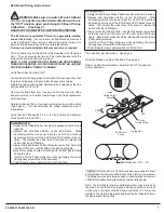
The time delay of the obstruction feature can be adjusted in the field
as required.
The unit has been factory-configured to respond
immediately to an obstruction.
In certain applications where
excessive wind or excessive stack pressure is present, a delay of 1,
3, or 5 seconds can be selected by toggling dip switches T1 and T2
on the ELS board.
Obstruction Operation:
TEACHING CLOSED AND OPEN DOOR POSITIONS:
5
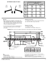
The following adjustments mechanical, hydraulic and electrical are
listed in a suggested sequence.
Make sure that power to unit is
.
• Set Closing Power. Use 11/16" wrench or socket. Turn Power
Adjustment Nut clockwise to increase door closing power. Door
control is shipped set at midpoint of power setting. Maximum
closing power can be achieved with 5 (360°) turns of the power
adjustment nut for a regular PowerMatic, 7 turns if unit is a
Barrier Free (BF) unit.
– Use 1/8" hex wrench
• Closing Cycle – Make adjustments, as necessary, to the Sweep
Speed "S" valve and Latch Speed "L" valve. See illustration on
Page 2. Turn valves clockwise to reduce speed, counter
clockwise to increase speed.
NOTE:
MECHANICAL ADJUSTMENT
HYDRAULIC ADJUSTMENT
OFF
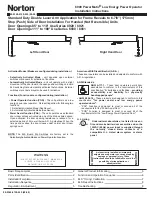
Adjustments for the PowerMatic Product
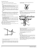
– Adjust "CL/AS DLY" Rotary Switch/Timer Pot on the printed
circuit board as necessary using a standard screwdriver with a
1/8" wide blade. Adjustable for 0 to 30 seconds (see chart
below).
– Power Assist Function Only:
Adjusts the length of time the motor will assist with opening
from the time the motor is activated.
– Power Operator Function Only:
Adjusts the length of time the door remains at the fully open
position after the operator function shuts off.
• Opening Cycle – Adjust Backcheck, "B" valve, as necessary, for
hydraulic resistance to door opening in the backcheck range. See
illustration on Page 2.
1/8"
Hex
Key
Slower
Closing
Faster
Closing
Closing Cycle
Closed
10°
L
a
tc
h
R
a
n
g
e
S
w
ee
p R
ang
e
1/8"
Hex
Key
Increase
Cushion
Decrease
Cushion
Opening Cycle
Backche
ck
O
p
e
ni
ng
Length of Time
(Seconds)
Setting
0
2
5
10
15
20
25
30
0
1
2
3
4
5
6
7
• If desired, install No. 668 Security Plate over notch in cover to
conceal the Selector Mode Switch when cover is installed.
• Install cover with mounting screws removed at beginning of
installation.
1
0 9
8
7
6
2
3
4
5
CL/AS DLY
S2
Illustration for CL/AS DLY
Rotary Switch/Timer Pot
From Printed Circuit Board
NOTE:
oo much Backcheck, "B" valve, can affect
he
operation of the units pump, preventing units rom fully
opening the door. This valve may requir fine tuning after all
other adjustments have bee made.
T
t
f
e
n
• Backcheck Position "P" valve is closed. Open by turning counter
clockwise, only if backcheck cushioning is required to begin at a
greater degree of door opening than the approximately 75° it is
set for.
ELECTRICAL:
Turn power input to unit on.
Selector Mode Switch – Set to the “ON” Position for normal use.
Time
B
ELS Dip Switch T1
B
ELS Dip Switch T2
1 Sec.
5 Sec.
Immediate
3 Sec.
A
A
B
B
A
A
Push And Go
A
ENABLED
DISABLED
B
ELS Dip #3 DN
Selectively Activated
Automatically Activated
Mode
Function
Power Operator
Power Assist
A
B
ELS Dip #4 PAS
Main Board Dip #1 P/A
OFF
ON
OBSTRUCTION DIP SWITCH SETTINGS:
!
Before operating, the PowerMatic 6900 must be “taught” the
fully closed and fully open door positions.
“
l
- Turn Power Input to Unit “ON”.
- With the door fully closed, press and release the BLACK
pushbutton on the ELS board. The ELS system will store this
position as closed and begin the 10 second “Teaching Mode”.
- Within the 10 second time frame, manually open the door to the
desired fully open position. While holding the door open in this
position, press and release the WHITE pushbutton on the ELS
board. The ELS system will store this position as open.
- Let the door return to the closed position.
This will end the
“Teaching Mode” regardless if the 10 second time frame has
elapsed.
- Set the Selector Mode Switch to the “ON” position for normal
operation or “H\O” for i
hold open.
-
If unit does not respond to teaching or if the ELS LED
began flashing when power input was first turned on and
continues to flash , see ELS Reset Instructions on page 8.
WARNING:
A
NOTE:
Verify that dip switch #3 on the ELS board is
in the “ ” position to disable the Push and Go Feature. Verify
the Selector Mode Switch is in the“OFF”position (Page 2)
• ELS board comes from factory with potentiometer timed” and
ready for unit to be taught open and c osed door positions.
•
ndefinite


