


80-9369-0120-020 (09-08)
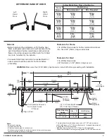
• Determine hand of door from illustration on Page 3.
• Using template, locate and prepare holes in the frame and door:
–
7/8" (22mm) diameter holes
for conduit, for power input and for switch/sensor wires.
On new construction these holes will generally be drilled by
the frame supplier at their shop or at the time the frame is installed in
the wall.
– Prepare
holes for 1/4-20 machine screws or
No. 14 x 2-3/4" (70mm) wood screws. Blind rivet nuts (by others) are
suggested for unreinforced hollow metal frames or for aluminum
frames.
– Prepare
holes for 3/8" diameter sex nuts. Standard units are
supplied with sex nuts and screws for 1-3/4" (44mm) thick door. Sex
nuts and screws for other door thicknesses are available to order.
• Remove cover from door operator assembly and set cover and cover
screws aside.
• Fasten backplate/control assembly to frame face
–
Connect conduit to backplate
fastening backplate to frame.
–
Fasten backplate to frame. Connect
conduit bracket, from screw pack, to the door control's backplate
with two (2) screws provided.Then connect wiring conduit to conduit
bracket on backplate.
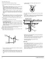
• Remove forearm screws from the arm adjusting rod and disassemble
the arm slide and shoe assembly from the arm assembly.
Series 6920 / 6921 Models Only.
IF frame reveal is less than 3-1/4” (83mm) use a saw and cut 1-7/8”
(48mm) off the end fo the adjusting rod.
Frame
Door
Concealed Wired Units Only: Two (2)
NOTE:
seven (7)
two (2)
Concealed Wired Units Only:
Surface Wired Units Only:
NOTE:
before
Installation Sequence
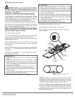
• Fasten arm slide and shoe assembly to the door with the long end of
arm shoe away from the hinge.
• Slide the main arm onto the pinion shaft of the door control unit at a
90° angle to the door control unit and frame. Align arm mark “S” with
the flat corner of the pinion shaft square (see illustration above
right).
•
Install and tighten 1/4-20 Flange Head Screw with 7/16”
wrench or socket.
• Open Door. Align and insert adjusting rod into the arm slide.
Close Door.
• Rotate the main arm away from the hinge until the adjusting rod
and arm slide are perpendicular (at a 90° angle) to the door.
Secure at 90° angle with the forearm screw.
• Adjust valves “S” and “L” using the 1/8” hex wrench provided. See
Hydraulic Adjustment Page 5
Note: A.D.A. Requires that from an open position of 70° the door
will take at least 3 seconds to move to a point 3” (75mm) from the
latched position, measured at the leading edge of the door.
• Make wire connections using Wiring Instructions
No. 80-9369-0901-020
IMPORTANT:
Power Operator Units Only:
Power Operator Units Only:
•
The opening speed of the door
from closed position to 80° must be 3 seconds or longer and 4
seconds or longer to the fully open position.
•
The force required to
a
door from opening or closing must not exceed a 15lbf. (67N)
applied 1" (25mm) from the latch edge of the door at any point in
the opening or closing cycle.
prevent
Left Hand Door Shown
Viewed from ceiling
Looking down on Unit
4
Adjusting
Rod
Arm
Slide
Door
Shoe
Main
Arm
R
L
Y
S
Z
Pinion
Flat
Arm Mark
Frame
Face
Frame
Reveal
Door


