


80-9369-0120-020 (09-08)
General
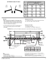
Fasteners for Frame
Hollow Metal Door Frame Reinforcing
Frame
Material
12 Ga.
.1046
14 Ga.
.0747
16 Ga.
.0598
18 Ga.
.0478
(2.66)
(1.90)
(1.52)
(1.21)
Recommended
12 Ga.
.1046
10 Ga.
.1343
10 Ga.
.1343
8 Ga.
.1644
(2.66)
(3.41)
(3.41)
(4.18)
Min. Required
18 Ga.
.0478
12 Ga.
.1046
12 Ga.
.1046
10 Ga.
.1343
(1.21)
(2.66)
(2.66)
(3.41)
Reinforcing
DETERMINE HAND OF DOOR
• Before beginning the installation, verify that the door
frame is properly reinforced and is well anchored in the
wall. Unreinforced hollow metal frames and aluminum
frames should be prepared and fitted with 1/4-20 blind
rivet nuts, furnished by the installer.
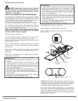
• Concealed electrical conduit and concealed switch or
sensor wires should be pulled to the frame before
proceeding.
• 1/4-20 Machine screws for hollow metal and aluminum.
• No. 14x2-3/4" (70mm) long wood screws.
Fasteners for Door
• 1/4-20 Machine screws.
• 3/8" diameter x 1-3/4" (45mm) long sex nut..
WARNING: Make sure that (120V, 60Hz) input power is turned off before proceeding with installation.
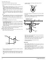
1/2
(13)
5/16
(8)
7-1/4
(184)
1-11/16
(43)
1-7/16
(37)
5/8
(16)
3/8
(10)
4.0
(102)
“A”
11-1/2
(292)
17-5/16
(440)
23-7/8
(606)
26.0
(660)
3/8
(10)
1-1/4
(32)
Notes:
• Do not scale drawing.
• Left hand door shown.
• All dimensions are given in inches (mm).
• Thickness recommended for reinforcements in hollow metal doors and
frames is charted at the top of this page.
• This template information based upon use of 5" (127mm) maximum
width butt hinges or 3/4" (19mm) offset pivots. A separate template will
be supplied for other conditions.
• Conduit hole farthest from hinge is suggested for 120 VAC power input.
• Maximum frame reveal is 6-7/8” (175mm) for this application.
1/4-20 Machine Screws or
No. 14 Wood Screws
(7 Places)
For Concealed Wired
Units Only (2 Places)
3/8 DIA.
Sex Nuts
(2 Places)
Door
Frame
Rabbet
Frame
Stop/Soffit
4-1/8
Unit Height
3
Left
Hand
Door
Right
Hand
Door
Door Opening
Angle
Dim – “A”
Unit Series
Up to 110°
111° to 180°
5-7/8 (150)
3-1/8 (80)
6930
6920
c
L
Hinge or Pivot
7/8”
(23)


