background image

Page 2

IMPORTANT INSTALLATION INFORMATION

FEATURES

All encoders have the following electrical features:
• Power (+DC)
• Common
• Output Signal(s)
Power (also referred to as supply, power source, and 

power +V/VCC) is DC for encoders. 

There-

fore, power should always be connected to the 

positive (+) side of DC power.

 In addition, encoder 

power should be regulated to within ±5% at the en-

coder and should be free of induced transients. Com-

mon (also referred to as Com, supply common, and 

ground) is generally a black wire (verify via Electrical 

Connections table). Common should always be con-
nected to the negative (-) side of DC power. 
All encoders have at least one output signal (A); how-

ever, it is common for encoders to have three signals 

A, B, Z (may also be referred to as C, X, or index). 

The outputs should each be connected to the receiv-

ing device at the appropriate terminal. NOTE: Never 

connect A, B, or Z to the + or - side of DC power. 

ELECTRICAL CONNECTIONS


Cable -

 The use of shielded cable is recommended 

for all encoder installations. When a Dynapar brand 

encoder is ordered, the type of termination is gener-

ally defined (usually the last selectable code in Order-

ing Information). If a code for a cable was indicated, 

the encoder was manufactured to include a shielded 

cable. If any other type of termination was selected or 

if selection of termi-nation type was not requested, a 

cable assembly must be ordered. (The cable assem-

bly easily hooks onto the encoder’s connector making 

it ready for wiring). 
To determine which cable assembly to order, refer 

to the Electrical Connections table (in the encoder’s 

manual). 

GENERAL GUIDELINES

Encoders provide quality measurements and long 

life when common sense, care, and accurate align-

ments are provided during installation. The following 

general guide-lines will help to ensure a trouble-free 

installation.

Mounting the Encoder

Wiring the Encoder

• Never connect or disconnect the encoder con-

nector or wiring while power is ON. Doing so may 

damage the encoder.
• Power should always be connected to the + side 

of DC power.
• Common should always be connected to the - 

side of DC power.
• Never connect A, B, or Z to the + or - side of DC 

power.

In some cases, there may be more than one table or 

the table may be broken into sections due to different 

output types. If so, refer to the information listed for 

the output type selected for the encoder (in Ordering 

Information). 
Wiring should be run through dedicated conduits or 

harnesses (not shared with any other wiring) which 

are spaced at least 12 inches apart. This protects the 

cable from physical damage while providing a degree 

of electrical isolation. Also, do not run cable in close 

proximity to other conductors which carry current to 

heavy loads such as motors, motor starters, contac-

tors, or solenoids. Doing so could result in electrical 

transients in the encoder cable which cause unde-

sired signal pulses. 

NOTE: Never connect or disconnect the encoder 

connector or wiring while power is ON. Doing so 

may damage the encoder.

Grounding - 

DO NOT ground the encoder through 

both the machine and the cable wiring. Connect the 

shield at the input device only. 

NOTE: If the shield 

is connected at both ends, grounding problems 

that degrade system performance may result.

For European-based applications requiring CE com-

pliance, cable length must not exceed 30m. Connect 

the shield to building ground on either the Encoder 

or Controls end. CE compliant products are tested to 

EN61326 EMC.

ELECTRICAL CONNECTIONS

 (cont.)

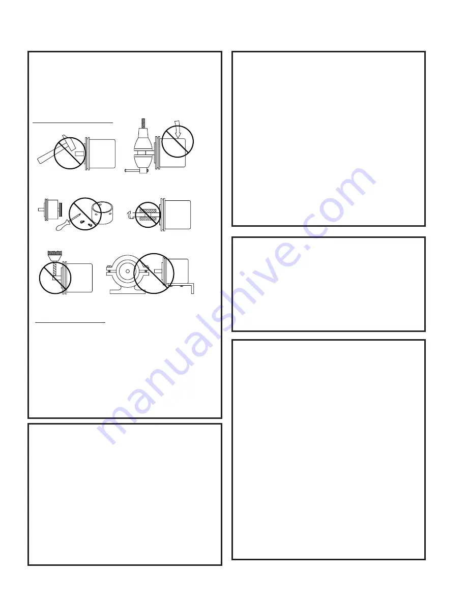
Do not shock the encoder.

Do not subject the encoder to

axial or radial shaft stresses.

Do not tool the encoder

or its shaft.

Do not use makeshift techniques

to mount the encoder.

Do not use a rigid coupling.

Do not disassemble the encoder.

Содержание NexGen SLIM Tach HT55

Страница 1: ...ion viewing the shaft clamp end of the encoder Quadrature Phasing 90 45 Symmetry 50 15 Number of Output Modules Single or Dual ELECTRICAL Input Power Requirements 5 26VDC 120mA typical per sensor module plus line driver load Output Signals IC WE Differential Line Driver 150mA sink or source Frequency Response 0 180kHz Data Index Noise Immunity Tested to EN61326 1 Electrical Immunity Reverse polari...

Страница 2: ...ollowing general guide lines will help to ensure a trouble free installation Mounting the Encoder Wiring the Encoder Never connect or disconnect the encoder con nector or wiring while power is ON Doing so may damage the encoder Power should always be connected to the side of DC power Common should always be connected to the side of DC power Never connect A B or Z to the or side of DC power In some...

Страница 3: ...them to the receiving device Any unused encoder signal wires must be individually insulated and tied back They should NEVER be in contact with common power sources or other output signal lines The encoder is correctly connected to the receiving device per the Electrical Specifications table and the receiving device s terminal strip label however it s counting in the wrong direction What s wrong In...

Страница 4: ... 12 mm 2 5 3 25 63 82mm 1 4 6 mm BOLT SIZE RECOMMENDED TORQUE 1 4 6mm 5 16 8mm 3 8 9 5mm 1 2 12mm 50 60 in lbs 70 80in lbs 100 125 in lbs 125 150 in lbs STEP 1 PREPARATION AND RECOMMENDED TOOLS Disconnect power from equipment and encoder cable Ensure that you have the proper tools Typical tools that may be needed depend ing on the options chosen are 2 Phillips Screwdriver 3mm Hex Wrench Caliper Ga...

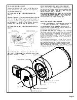
Страница 5: ... STEP 9 GOOD INSTALLATION CHECK POINT Follow the 3 step installation check to ensure a good installation thus far Refer to figure above for key reference dimensions A Check clearances from mounting face Ensure you have a minimum clearance of 1 16 between the encoder shaft and any non rotating surface closest to the encoder shaft B Check tether installation Make sure that the tether is unstressed T...

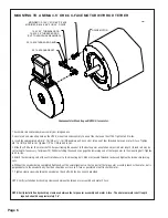
Страница 6: ... threaded holes on motor C Face Tighten 3 8 16 UNC to 200 in lbs Tighten 1 2 13 UNC to 500 in lbs 4 Slide the HT55 over the motor shaft After positioning the encoder to the best angular orientation adjust rod arm length thread rod may be cut to length if necessary for proper fit While installing the encoder engage the remaining end of the torque arm to the mounting bolt Tighten to 40 in lbs 5 Atta...

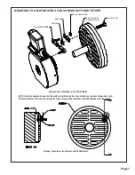
Страница 7: ...unting on Fan Shroud Motor Cutaway Side View of the Bracket and Bolt Attachment C SIZE TOLERANCES UNLESS INDICATED C D T C TITLE DRAWING NUMBER UL RoHS R CE CSA TUV ATEX TM 23 JAN 2020 ROD_TETHER 1 OF 1 RELEASED DATE SHEET CHECKED DATE APPLICATION 23 JAN 2020 PRO E MODEL ROD_TETHER 005 01 1 4 DRAWN DATE X X FINISH ROD_TETHER 1 4 XXX XX ANGLES FILE NAME SCALE COMPLIANCE REQUIRED MATERIAL UNITS INCH...

Страница 8: ...stalling the encoder engage the torque arm by inserting the 10 32 x 1 2 hex bolt into the tapped hole in the bracket Tighten to 40 in lbs 5 Without the encoder being completely tightened set the axial alignment so that no part of the torque arm assembly touches the motor but is perpendicular to the encoder body Position should be as close to C face as possible but not flush with motor 6 Tighten 10...

Страница 9: ... EN61326 1 EMC In all cases system CE compliance is ultimately the responsibility of the manufacturer integrating the encoder 1 3 QUICK RELEASE CONNECTOR HOOD WIRING To install the Quick Release Connector perform the following steps 1 Remove the four screws from the mating connector housing that hold the terminal block in place Re move terminal block from housing 2 Insert wiring through liquid tig...

Страница 10: ...5V out Line Driver IC WE Code 7 Output 1 Single 2 Dual Isolated Differential bidirectional signals A A B B For additional bore sizes available please consult factory M12 12mm M14 14mm M15 15mm M16 16mm M18 18mm M20 20mm M25 25mm M45 45mm M50 50mm M55 55mm Code 8 Fixing Stamped Metal Available when shaft is 1 25 or smaller 1 4 5 C Face Tether 2 8 5 C Face Tether 3 Slotted Tether Swivel Rod A Rod Te...

Страница 11: ... 2 B C D 200 5 08 24X 15 2X 45 X 125 3 17 90 0 114573 0001 Tether Kit 530 13 46 Ø3 500 88 9 Ø2 506 63 65 Ø 53 13 46 2 94 74 68 Ø 82 20 83 1 25 31 75 24X ON 3 000 76 2 B C D Ø 20 51 24X 15 2 350 59 7 90 0 530 13 46 Ø3 500 88 9 Ø2 510 63 75 3 525 89 54 ON 3 000 B C 76 2 24X Ø 20 5 08 24X 15 25 6 35 1 25 31 75 75 19 05 2 14 54 36 625 15 88 90 0 4 5 C Face Tether Slotted Tether 8 5 C Face Tether ...

Страница 12: ...Y Worldwide Brands NorthStarTM DynaparTM HengstlerTM HaroweTM Technical Support Tel 1 800 234 8731 Fax 1 847 662 4150 northstar techsupport dynapar com C SIZE TOLERANCES UNLESS INDICATED C D T C TITLE DRAWING NUMBER UL RoHS TUV CE CSA FCC VCCI ATEX TM 8 29 210 6 4 71 119 6 1 75 44 5 1 95 49 5 2 50 63 5 1 16 29 5 4 00 101 6 4 20 106 7 5 80 147 4 3 38 85 8 2 35 59 8 120 4X 30 5 70 144 8 RELEASED DAT...

Отзывы: