10
Wiring the Controller to the Opener
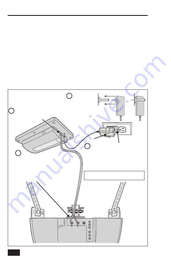
The Garage Door Controller wires to the garage door opener with a two wire connection.
1.
Connect the GD00Z-8-ADT connection wires to the two pushbutton terminals on the garage door
opener. The terminals on various models may have different names. Either wire can connect to
either terminal.
✓
IMPORTANT!
Be sure the wires clear all moving parts of the door and opener.
Connecting the Power Supply
2.
Plug the Power Supply’s cord into the jack on the Garage Door Controller.
3.
Join the Power Supply with the Adapter.
4.
Remove the outlet faceplate screw. Plug the Power Supply and bracket into a 115 VAC outlet.
Align the bracket hole to the outlet hole and secure.
Be sure the outlet is powered at all times
and not controlled by a switch
.
Secure the bracket with the provided zip tie strap.
✓
IMPORTANT!
Do not disconnect any wires currently connected to the Garage Door Opener.
Controller Connections
Figure 6. Controller Mounting
PU
SH
BU
TT
ON
PU
SH
BU
TT
ON
GARAGE
DOOR
OPENER
Connect the GD00Z-8-ADT connection
wires to the push-button wall console
terminals on the garage door opener.
The terminals may be named "PWC", "WC",
"PB", "PUSHBUTTON", or "RED and WHITE".
Terminal names and locations vary by model.
DO NOT DISCONNECT ANY WIRES CURRENTLY
CONNECTED TO THE GARAGE DOOR OPENER.
Remove the screw from 120 VAC
outlet faceplate. Plug in the adapter.
Secure the power adapter to the faceplate
with the provided screw.
Feed the zip tie through the two holes in the
bracket and secure.
USE WIRE TIES TO SECURE
EXCESS WIRING CLEAR
OF ALL MOVING PARTS
OF THE GARAGE
DOOR AND OPENER
Either wire can
connect to either
terminal
Plug the power cord
Carefully join the
power suppy with
the bracket.
into the power input
jack on the GD00Z-8-ADT
2
1
4
3


