Nortec MH Series Скачать руководство пользователя страница 32


10-10 

Page 28 
2008-12-03


Figure 9.   Mounting Process – Step 9

 
Assemble the drains according to the corresponding figure above (the drains can be assembled 
for draining to the right or to the left) and fix it to the water tank 

using the mounting bracket provided.


Содержание MH Series

Страница 1: ...2544832 A MH Series EVAPORATIVE HUMIDIFIER COOLER Installation Manual TM ...

Страница 2: ...NOTICE WALTER MEIER LTD does not accept any liability for installations of humidity equipment installed by unqualified personnel or the use of parts components equipment that are not authorized or approved by WALTER MEIER LTD COPYRIGHT NOTICE Copyright 2008 WALTER MEIER LTD All rights reserved RECORD OF REVISIONS For each revision put the revised pages in your manual and discard the superseded pag...

Страница 3: ...NG AND INSTALLATION WORK 18 1 2 UNIT MOUNTING 19 10 20 PLUMBING AND ELECTRICAL INSTALLATION 1 WATER INSTALLATION 34 1 1 OVERVIEW WATER INSTALLATION 34 1 2 NOTES ON WATER INSTALLATION 35 1 3 ELECTRICAL INSTALLATION 36 10 30 OPERATION 1 OPERATION 42 1 1 PUTTING INTO OPERATION 42 1 2 ADJUST THE VOLUME CONTROLLING VALVES 42 1 3 NOTES ON OPERATION 43 1 4 TAKING OUT OF OPERATION 43 10 40 MAINTENANCE TRO...

Страница 4: ...2008 08 28 3 TAKING OUT OF SERVICE DISPOSAL 52 3 1 TAKING OUT OF SERVICE 52 3 2 DISPOSAL RECYCLING 52 4 PRODUCT SPECIFICATIONS 53 4 1 TECHNICAL DATA 53 4 2 UNIT DIMENSIONS 54 WARRANTY ...

Страница 5: ...10 00 Page 1 2008 12 03 10 00 INTRODUCTION ...

Страница 6: ...ontact your Nortec representative They will be glad to assist you 1 2 NOTES ON THE INSTALLATION OPERATING INSTRUCTIONS Limitation The product covered in this installation and operating instruction manual is solely the Nortec MH Adiabatic Air Humidifier The various accessories associated with the Nortec MH Adiabatic Air Humidifier are only described in such detail that is necessary for proper opera...

Страница 7: ...y lead to severe injury or even death of persons Safekeeping Please safeguard these installation and operating instructions in a safe place where they can be immediately accessed If the equipment changes hands the documentation must be passed on to the new operator If the documentation gets misplaced please contact your Nortec representative Copyright protection The present installation and operat...

Страница 8: ...l trained and adequately qualified and is authorized by the customer For safety and warranty reasons any action beyond the scope of this manual must be carried out only by qualified personnel authorized by the manufacturer It is assumed that all persons working with the Nortec MH are familiar and comply with the appropriate regulations on work safety and the prevention of accidents Intended use Th...

Страница 9: ...ption emits harmful UV C rays If the UV lamp is operated outside the housing the emitted UV C rays may damage the eyes Prevention Never operate the UV lamp outside the housing Warning Badly maintained humidifiers can endanger the health If the unit is not properly maintained germs may grow in the water tub which can cause illness and the humidification boxes and the mist eliminator of the Nortec M...

Страница 10: ... to the unit No modifications must be undertaken on the Nortec MH without the express written consent of the manufacturer For the replacement of defective components use exclusively original accessories and spare parts available from your Nortec supplier 3 PRODUCT OVERVIEW 3 1 MODEL OVERVIEW The Nortec MH is available in the two base versions flow with direct water system and Reflow with circulati...

Страница 11: ...10 00 Page 7 2008 12 03 3 2 PRODUCT DESIGNATION The product designation and the most important unit data are found on the rating plate 3 3 TYPE KEY ...

Страница 12: ...ide thread 2 Volume controlling valves adjustable manually 3 Water tub 4 Open drain 1 5 PVC 1 66 42 mm OD 5 Water hoses 6 Spray bar cap with distribution pipes 7 Humidification boxes 8 Mist eliminator for air speed above humidification boxes 3 8 m s 750 fpm 9 Control unit on off Figure 1 Construction Model MHB Flow ...

Страница 13: ...opens and the water flows via the pressure reducing valve accessory the water filter accessory and the manually adjustable volume controlling valves to the distribution pipes above the humidification boxes The distribution pipes evenly supply the water to the entire surface of the humidification boxes where it flows down and humidifies the air flowing through the humidification boxes The excess wa...

Страница 14: ...ves adjustable manually 3 Step valves 1 to 3 4 Water tub 5 Open drain outside diameter 1 5 PVC 1 66 42 mm OD 6 Water hoses 7 Spray bar cap with distribution pipes 8 Humidification boxes 9 Mist eliminator for air speed above humidification boxes 750 fpm 3 8 m s 10 UV water treatment option 11 MHTC Total Control Unit Figure 3 Construction Model MHTC Flow ...

Страница 15: ...y compared to the MHB Flow model In case of a humidification cooling request one two or all three step valves open depending on the request The water flows via the manually adjustable volume controlling valves to the distribution pipes above the humidification boxes The distribution pipes evenly supply the water to the entire surface of the humidification boxes where it flows down and humidifies t...

Страница 16: ...olled supply valve 3 Circulation pump 4 Overflow 5 Drain 6 Drain valve 7 Volume controlling valves adjustable manually 8 Water tub 9 Water hoses 10 Spray bar caps with distribution pipes 11 Humidification boxes 12 Mist eliminator for air speed above humidification boxes 750 fpm 3 8 m s 13 MHB Control Unit Figure 5 Construction Model MHB Reflow ...

Страница 17: ...ovides On Off control by means of the MHB control unit and an external On Off humidistat In case of a humidification cooling request the pump is activated The water flows via the manually adjustable volume controlling valves to the distribution pipes above the humidification boxes The distribution pipes evenly supply the water to the entire surface of the humidification boxes where it flows down a...

Страница 18: ...tion pump 4 Overflow 5 Drain 6 Drain valve 7 Step valves 1 to 3 8 Volume controlling valves adjustable manually 9 Water tub 10 Water hoses 11 Spray bar cap with distribution pipes 12 Humidification boxes 13 Mist eliminator for air speed above humidification boxes 750 fpm 3 8 m s 14 UV water treatment option 15 MHTC Total Control Unit Figure 7 Construction Model MHTC Reflow ...

Страница 19: ...ply valve opens until the upper limit is reached again The MHTC Reflow model provides multistep control by means of the MHTC Total Control unit and the step valves 1 2 or 3 step valves depending on the humidifier capacity The MHTC Total Control unit for wall mounting processes analog sensor control signals and uses them to control the step valves This allows multistep control 1 to 3 steps dependin...

Страница 20: ...optional UV water treatment a particular amount of water is led to the UV water treatment unit where it is sterilized 3 8 STANDARD DELIVERY Standard delivery includes Nortec MH Adiabatic Air Humidifier according to type designation disassembled equipped with options according to packing list Ordered accessories with operating instructions packed separately Installation and operating instructions t...

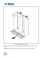
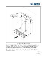
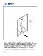
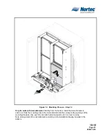
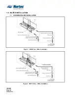
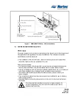
Страница 21: ...10 10 Page 17 2008 12 03 10 10 INSTALLATION ...

Страница 22: ...regulations dealing with water and electrical installations Safety The electrical installation for the unit models MHB Flow MHTC Flow MHB Reflow MHTC Reflow requires the removal of the control unit cover Please note the following Danger of electrical shock You may get in touch with live parts when the control unit is open The control unit must be connected to the mains only after all mounting and ...

Страница 23: ...lter must be installed at the air inlet of the humidification unit The filter must meet the quality standards MERV 11 Note WMCI specifies EU7 f7 which is equivalent to MERV 11 ASHRAE 52 2 or better In case of low ambient temperature the duct must be insulated to prevent the moist air from condensing inside the duct If the system is equipped with a heater make sure it is at least 20 0 5 m away from...

Страница 24: ...ocess Step 1 Align the water tub to the centre of the duct then use a level check water tub to the duct lengthwise and crosswise Shim the tank as required until it is level Note Install four self tapping screws 1 4 UNC x 3 4 on each side of the tub to secure it in place ...

Страница 25: ...10 10 Page 21 2008 12 03 Figure 2 Mounting Process Step 2 Fix the cross beam B to the water tub using four hexagon socket screws 1 4 UNC x 1 2 and washers ...

Страница 26: ...efer to step 7 for more information Carefully mount the left D and the right vertical support E onto the threaded bolts of the water tank then fix each support with four 1 4 UNC nuts and washers do not overtighten the nuts Important Before tightening the nuts make sure the holes of the vertical supports seat solidly on the sheet metal of the water tub and do not stuck on the collar of the threaded...

Страница 27: ...he water tub then fix each support with two 1 4 UNC nuts and washers to the water tub do not overtighten the nuts and with a hexagon socket screw 1 4 UNC x 1 2 and a washer to the cross beam Important Before tightening the nuts make sure the holes of the intermediate support seat solidly on the sheet metal of the water tub and do not stick on the collar of the threaded bolt ...

Страница 28: ...ure 5 Mounting Process Step 5 Fix the front bracket G to each vertical support using two hexagon socket screws 1 4 UNC x 1 2 and washers Important Before tightening the screws make sure all supports are vertically exactly aligned ...

Страница 29: ...washer see figure above Important With multiple intermediate supports all mounting brackets must be mounted to the supports on the same side The mounting brackets fixed to the outermost supports must be mounted always outside between duct wall and support and point inward Finally align the supports then fix the mounting brackets to the duct ceiling using two self tapping screws 1 4 UNC x 3 4 each ...

Страница 30: ... the EPDM sealing profiles to the outermost vertical supports and to the front bracket using the clamping brackets and self tapping screws 10 x 3 4 supplied Tailor the EPDM sealing profiles to the duct height and the duct width then fix them to the duct walls and the duct ceiling using the clamping brackets and self tapping screws 10 x 3 4 supplied number of self tapping screws to be used as requi...

Страница 31: ... Step 8 Fix hydraulic unit to the water tub and the cross beam using four hexagon socket screws 1 4 UNC x 1 2 and washers Important Remove the closing plug H from the circulation pump inlet before mounting the hydraulic units MHB Reflow or MHTC Reflow ...

Страница 32: ...gure 9 Mounting Process Step 9 Assemble the drains according to the corresponding figure above the drains can be assembled for draining to the right or to the left and fix it to the water tank using the mounting bracket provided ...

Страница 33: ...the corresponding openings of the supports then push the humidification box downwards until it comes to a stop arrangement of the humidification boxes according to the installation drawing included in the delivery NOTE In systems with an air speed 925 fpm 4 7 m s through the boxes the cover sheet K must be mounted to all topmost humidification boxes before installing them ...

Страница 34: ...k the mounting brackets into corresponding openings of the vertical supports then push the brackets downwards until it comes to a stop if necessary use a rubber mallet Note arrangement of the mounting brackets according to the detail figures above and the installation drawing included in the delivery ...

Страница 35: ...ottom install the mist eliminator in each row Hook the mounting clips of the mist eliminator into the corresponding openings of the mounting brackets then push the mist eliminator downwards until it comes to a stop Note arrangement of the mist eliminator according to the installation drawing included in the delivery ...

Страница 36: ...g hood underneath the frame sheet of the humidification box see detail above then pivot the spray cap bars downwards The two brackets on the front side of the spray cap bar must engage in the frame see detail above of the humidification box Note arrangement of the spray cap bars according to the installation drawing included in the delivery ...

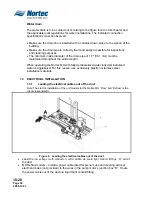
Страница 37: ...10 20 Page 33 2008 12 03 10 20 PLUMBING ELECTRICAL INSTALLATION ...

Страница 38: ...10 20 Page 34 2008 12 03 1 0 WATER INSTALLATION 1 1 OVERVIEW WATER INSTALLATION Figure 1 MHB Flow Water Installation Figure 2 MHTC Flow Water Installation ...

Страница 39: ...ec MH use exclusively untreated drinking water Reverse Osmosis Water fully demineralised water or partly softened water The use of additives such as corrosion inhibitors disinfectants etc is not allowed since these additives may endanger health and affect proper operation If the Nortec MH shall be operated with softened water please contact your Nortec supplier The connection material must be pres...

Страница 40: ...rating the Nortec MH with fully demineralised water fully demineralised water is aggressive For this reason use exclusively plastic or stainless steel installation materials 1 3 ELECTRICAL INSTALLATION 1 3 1 Leading the electrical cables out of the duct Note The electric installation of the unit models for the Nortec MH Flow and Reflow is the clients responsibility Figure 4 Leading the electrical ...

Страница 41: ...ables from the hydraulic unit to the corresponding terminals in the control unit according the appropriate wiring diagram Important all cables must be lead into the control unit via strain reliefs installed into the openings in the bottom of the control panel housing 3 MH Reflow models Connect the power cable from the pump motor to the corresponding terminals according to the appropriate wiring di...

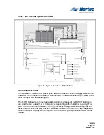
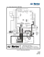
Страница 42: ...10 20 Page 38 2008 12 03 1 3 3 Wiring Diagram Nortec MH Flow Figure 7 Wiring Diagram MH Flow ...

Страница 43: ...10 20 Page 39 2008 12 03 1 3 4 Wiring Diagram Nortec MH Reflow Figure 8 Wiring Diagram MH Reflow ...

Страница 44: ...10 20 Page 40 2008 12 03 THIS PAGE INTENTIONALLY LEFT BLANK ...

Страница 45: ...10 30 Page 41 2008 12 03 10 30 OPERATION ...

Страница 46: ...ad through cable glands Open the shut off valve in the water supply line Switch on the service switch in the mains supply Models MHTC Flow MHB Reflow MHTC Reflow switch on the MH control unit the unit switch lights up Note regarding the operation of the MH control unit please observe the information given in the separate operating instructions to the MH control unit Check the settings of the humid...

Страница 47: ...ation e g to perform maintenance works to eliminate a malfunction etc perform the following steps Close the shut off valve in the water supply line Models MHB Reflow and MHTC Reflow empty the water tub Models MHB Reflow and MHTC Reflow Start manual draining see operating instructions of the MH control unit and wait until the water tub is empty Models MHTC Flow MHB Reflow and MHTC Reflow switch off...

Страница 48: ...10 30 Page 44 2008 12 03 THIS PAGE INTENTIONALLY LEFT BLANK ...

Страница 49: ...10 40 Page 45 2008 12 03 10 40 MAINTENANCE TROUBLESHOOTING ...

Страница 50: ...bed intervals the cleaning work must be carried out correctly and the humidification boxes and the mist eliminator boxes must be replaced after their prescribed lifetime has elapsed WARNING If the unit is insufficiently maintained germs which can cause illness may grow in the water tub and the humidification boxes and the mist eliminator of the Nortec MH and may affect the air passing through the ...

Страница 51: ...at least MERV 11 according to ASHRAE 52 2 Standard Water tank Check water tank for soiling dust slime mineral deposit etc and clean with a combined detergent and disinfectant Note The actual hygiene status indicates whether the maintenance interval time must be decreased or increased Frame structure Check screw connections of the frame structure tight loose screw connections Clean frame structure ...

Страница 52: ...r mineral deposit If necessary dismantle the water distribution pipes and remove the mineral deposit Clean spray bar cap and water distribution pipes with a combined detergent and disinfectant Drain line with Siphon Check and clean with a combined detergent and disinfectant if necessary UV water treatment Option Dismantle the UV lamp Carefully clean glass tube and UV lamp After max of 8000 operati...

Страница 53: ...om the top remove the mist eliminator boxes push box upwards and remove it to the front 4 Release the fixing clip in the middle of the mounting bracket by pressing slightly on the vertical support then carefully push the mounting bracket upwards and remove it Repeat this step for all mounting brackets 5 Starting from the top remove the humidification boxes push box upwards and remove it to the fro...

Страница 54: ...p out of the housing 3 Remove glass tube to the top 4 Clean glass tube outside and inside with a lint free and soft cloth The installation of the UV lamp follows the reverse dismantling order CAUTION When installing the UV lamp make sure to hold the lamp until it is completely inserted Under no circumstances let the lamp fall inside the holder since this could damage the lamp ...

Страница 55: ...stream the Nortec MH Air velocity above the humidification boxes is too high Units without mist eliminator max 750 Fpm 3 8 m s Units with a 4 100 mm mist eliminator max 885 fpm 4 5 m s with a 7 87 200 mm mist eliminator max 1082 fpm 5 5 m s Install mist eliminator or reduce air velocity in the duct Water drain is leaking Check seal water drain Humidity Cooling demand present however the Nortec MH ...

Страница 56: ...air faults Faults relating to electrical installation must only be carried out by authorized personnel or your Nortec representative s service technician Repair work and replacement of faulty components must only be carried out by your Nortec representative s service technician 3 0 TAKING OUT OF SERVICE DISPOSAL 3 1 TAKING OUT OF SERVICE If the Nortec MH must be replaced or if the humidification s...

Страница 57: ...4 100 mm mist eliminator 5 5 m s Water supply R outside thread Water drain 1 5 PVC 1 66 42 mm OD outside diameter of tube Admissible water supply pressure Admissible water temperature 41 113ºF 5 45ºC Water quality Tap water Reverse Osmosis softened or fully demineralized water Pressure drop Typically 0 44 IWC 500 fpm 90 rh Admissible ambient temperature Control unit 34 104ºF 1 40ºC 34 104ºF 1 40ºC...

Страница 58: ...nts of 3 94 UD Max humidification efficiency Depth Humidification box Depth Mist eliminator Depth UD 85 8 200 mm 22 5 573 mm 85 8 200 mm 4 100 mm 22 5 573 mm 85 8 200 mm 26 5 673 mm 95 12 300 mm 26 5 673 mm 95 12 300 mm 4 100 mm 26 5 673 mm 95 12 300 mm 30 4 773 mm UA MHB MHTC Flow 3 8 97 mm MHB MHTC Reflow 5 9 131 mm ...

Страница 59: ...u of all other warranties expressed or implied by law No liability whatsoever shall be attached to THE COMPANY until said products have been paid for in full and then said liability shall be limited to the original purchase price for the product Any further warranty must be in writing signed by an officer of THE COMPANY 4 THE COMPANY s limited warranty on accessories not of the companies manufactu...

Страница 60: ...tor Avenue Ogdensburg NY 13669 TEL 1 866 NORTEC 1 EMAIL northamerica climate waltermeier com WEBSITE www humidity com CANADA Walter Meier Climate Canada Ltd 2740 Fenton Road Ottawa ON K1T 3T7 TEL 1 866 NORTEC 1 FAX 613 822 7964 Authorized Agent ...

Отзывы: