background image

22

 Key No.  Qty. 

Description

 Key No.  Qty. 

Description

  1 

Frame

  2 

Rail

  3 

Stabilizer

  4 

Left Fan

  5 

Seat Carriage

  6 

Deflector

  7 

Right Shield

  8 

Left Shield

  9 

Resistance Handle

  10 

Strap Grommet

  11 

Bungee Cord

  12 

Strap

  13 

Row Bar

  14 

Grip

  15 

Row Bar Cap

  16 

Footrest Strap

  17 

Right Footrest

  18 

Right Foot Pad

  19 

Right Footrest Bracket

  20 

Left Footrest Bracket

  21 

Left Footrest

  22 

Left Foot Pad

  23 

Seat

  24 

Set Screw

  25 

Snap Ring

  26 

Hub

  27 

Bearing

  28 

Bearing Spacer

  29 

Pulley Assembly

  30 

Axle

  31 

Pivot Bushing

  32 

Stop

  33 

Bumper

  34 

Rail Handle

  35 

Folding Clamp

  36 

Rail Foot

  37 

Small Carriage Roller

  38 

Rail Cap

  39 

Large Carriage Roller

  40 

Carriage Axle

  41 

Stabilizer Foot

  42 

Wheel

  43 

Storage Foot

  44 

Rail Pulley

  45 

Strap Roller

  46 

Strap Axle

  47 

Reed Switch/Wire

  48 

Frame Pulley

  49 

Frame Foot

  50 

Clamp

  51 

Row Bar Rest

  52 

Frame Handle

  53 

Pivot Axle

  54 

12 

Deflector Bracket

  55 

Pulley Bracket

  56 

6mm Washer

  57 

M6 Locknut

  58 

M8 Washer

  59 

M8 x 12mm Screw

  60 

M10 x 40mm Bolt

  61 

M10 x 20mm Screw

  62 

5mm Washer

  63 

M5 x 10mm Screw

  64 

#8 x 3/4" Screw

  65 

12 

M6 x 15mm Screw

  66 

M10 x 20mm Screw

  67 

Clip

  68 

14 

M4 x 16mm Screw

  69 

34 

M4 x 19mm Screw

  70 

M4 x 10mm Screw

  71 

M8 x 50mm Screw

  72 

Right Fan

  73 

8mm Washer

  74 

M10 Washer

  75 

Console

  76 

Neck

  77 

Upright

  78 

Knob

  79 

Wire Grommet

  80 

Right Upright Cover

  81 

Left Upright Cover

  82 

M8 x 35mm Screw

  83 

M8 x 50mm Hex Bolt

  84 

Upright Wire

  85 

Magnet

  86 

M8 Locknut

  87 

12 

M4 x 10mm Flat Head Screw

  * 

– 

User’s Manual

  * 

– 

Assembly Tool

PART LIST

Model No. NTRW5914.0 R0315A

Note: Specifi cations are subject to change without notice.


For information about ordering replacement parts, see 

the back cover of this manual. *These parts are not illustrated.

Содержание RW200

Страница 1: ...ons in this manual before using this equipment Keep this manual for future reference To register your product and activate your warranty today go to www nordictrackservice com registration For service at any time go to www nordictrackservice com Or call 1 800 TO BE FIT 1 800 862 3348 Mon Fri 6 a m 6 p m MT Sat 8 a m 12 p m MT Please do not contact the store ACTIVATE YOUR WARRANTY CUSTOMER CARE ...

Страница 2: ...r of this manual and request a free replacement decal Apply the decal in the location shown Note The decal s may not be shown at actual size WARNING DECAL PLACEMENT 2 IMPORTANT PRECAUTIONS 3 BEFORE YOU BEGIN 5 ASSEMBLY 6 HOW TO USE THE ROWER 10 FCC INFORMATION 17 MAINTENANCE AND TROUBLESHOOTING 18 EXERCISE GUIDELINES 19 PART LIST 22 EXPLODED DRAWING 23 ORDERING REPLACEMENT PARTS Back Cover LIMITED...

Страница 3: ...ndoors away from moisture and dust Do not put the rower in a garage or covered patio or near water 6 Place the rower on a level surface with a mat beneath it to protect the floor or carpet Make sure that there is at least 2 ft 0 6 m of clear ance around the rower 7 Inspect and properly tighten all parts regu larly Replace any worn parts immediately 8 Keep children under age 12 and pets away from t...

Страница 4: ...UTS 4 all STANDARD SERVICE PLANS ...

Страница 5: ...uestions after reading this manual please see the front cover of this manual To help us assist you note the product model number and serial number before contacting us The model number and the location of the serial number decal are shown on the front cover of this manual Before reading further please review the drawing below and familiarize yourself with the labeled parts Folding Clamp Rail Handl...

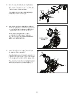
Страница 6: ...es not shown attached to the rower remove and discard the shipping tubes and the hardware attaching them With the help of a second person pull the Rail 2 outward and rotate the Stabilizer 3 downward 2 3 1 Go to www nordictrackservice com registration on your computer and register your product activates your warranty saves you time if you ever need to contact Customer Care allows us to notify you o...

Страница 7: ...step Attach the Stabilizer 3 to the Frame 1 with two M10 x 20mm Screws 61 Then hold the Rail Handle 34 pull the Rail 2 outward and rest the Rail on the floor 61 3 4 Orient the Seat 23 as shown and slide the Seat Carriage 5 onto the Rail 2 4 23 2 2 5 34 3 1 ...

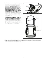
Страница 8: ...into the Frame Tip Avoid pinching the wires Attach the Upright 77 to the Frame 1 with four M8 x 35mm Screws 82 start all the Screws before fully tightening them 7 Identify the Right and Left Upright Covers 80 81 and orient them as shown Press the Right and Left Upright Covers 80 81 together around the Upright 77 and attach them to the Upright with two M4 x 19mm Screws 69 Then insert the Knob 78 in...

Страница 9: ...dam age the console displays or other electronic components Remove the screws and the battery covers insert batteries into the battery compartments and then reattach the battery covers Make sure to orient the batteries as shown by the diagrams inside the battery compartments To purchase an optional power adapter call the telephone number on the cover of this manual To avoid damaging the console us...

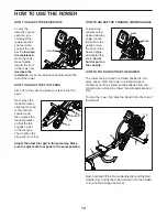
Страница 10: ...oot pad in the same way Make sure to adjust both foot pads to the same position HOW TO ADJUST THE CONSOLE VIEWING ANGLE To adjust the console to the desired viewing angle loosen the knob in the upright move the neck to the desired angle and tighten the knob do not hold or pull on the console HOW TO FOLD AND STORE THE ROWER The rower can be stored in a folded position to con serve space Store the r...

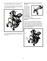
Страница 11: ...d lift the rail until the rower will roll on the wheels Then carefully move the rower to the desired location and lower the rail to the floor Do not hold or pull on the console when moving the rower HOW TO MOVE THE ROWER IN THE FOLDED POSITION See HOW TO FOLD AND STORE THE ROWER on page 10 and fold the rower Then hold the frame handle place your foot on a stabilizer foot and tip the rower until it...

Страница 12: ...e is the DRIVE Push backward with your legs Lean back slightly at the hips not at the waist keeping your back straight As you straighten your legs pull the row bar toward your chest Keep your elbows outward 3 The third phase is the FINISH Your legs should be nearly straight Continue to pull the row bar until your hands are even with your chest After the finish phase extend your arms forward and pu...

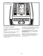
Страница 13: ... you to maintain a target watts output as it guides you through an effective workout You can even connect your MP3 player or CD player to the console sound system and listen to your favorite music or audio books while you exercise To use the manual mode see page 14 To use the sound system see page 15 To use a preset workout see page 16 Note Before using the console make sure that batteries are ins...

Страница 14: ...te SPM This mode shows the number of rowing strokes you are completing per minute Time This mode shows the elapsed time During a preset workout this mode shows the time remaining in the workout instead of the elapsed time Watts This mode shows your approximate power output in watts Watts meter This mode shows a visual representa tion of your power output in watts As you increase or decrease your p...

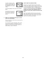
Страница 15: ...console buttons are not pressed for a few minutes the power will turn off automatically to save the batteries HOW TO USE THE SOUND SYSTEM To play music or audio books through the console sound system while you exercise plug a 3 5 mm male to 3 5 mm male audio cable not included into the jack on the console and into a jack on your MP3 player CD player or other personal audio player make sure that th...

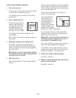
Страница 16: ... workout Each workout is divided into one minute segments A watts target is programmed for each segment Note The same watts target may be programmed for consecutive segments At the end of each segment of the workout a series of tones will sound The watts target zone will be shown in the watts target meter in the upper display The space between the flashing bars represents the watts target for the ...

Страница 17: ... equipment does cause harmful interference to radio or television reception which can be determined by turning the equipment off and on try to correct the interference by one or more of the following measures Reorient or relocate the receiving antenna Increase the separation between the equipment and the receiver Connect the equipment into an outlet on a circuit different from that to which the re...

Страница 18: ...ove the resistance handle and the right and left shields as described below See the EXPLODED DRAWING on page 23 Remove the six M4 x 10mm Screws 70 and then gently remove the Resistance Handle 9 Next remove the four M4 x 19mm Screws 69 and the ten M4 x 16mm Screws 68 from the Right and Left Shields 7 8 Then gently remove the Right and Left Shields Locate the Reed Switch 47 Turn the Left Fan 4 until...

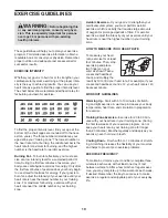
Страница 19: ...rm aerobic exercise which is activity that requires large amounts of oxygen for prolonged periods of time For aerobic exercise adjust the intensity of your exercise until your heart rate is near the highest number in your training zone HOW TO MEASURE YOUR HEART RATE To measure your heart rate exercise for at least four minutes Then stop exercising and place two fingers on your wrist as shown Take ...

Страница 20: ...illes Stretch With one leg in front of the other reach forward and place your hands against a wall Keep your back leg straight and your back foot flat on the floor Bend your front leg lean forward and move your hips toward the wall Hold for 15 counts then relax Repeat 3 times for each leg To cause further stretching of the achilles tendons bend your back leg as well Stretches Calves achilles tendo...

Страница 21: ...21 NOTES ...

Страница 22: ... 2 Strap Axle 47 1 Reed Switch Wire 48 1 Frame Pulley 49 1 Frame Foot 50 1 Clamp 51 1 Row Bar Rest 52 1 Frame Handle 53 1 Pivot Axle 54 12 Deflector Bracket 55 2 Pulley Bracket 56 6 6mm Washer 57 7 M6 Locknut 58 3 M8 Washer 59 2 M8 x 12mm Screw 60 1 M10 x 40mm Bolt 61 2 M10 x 20mm Screw 62 8 5mm Washer 63 8 M5 x 10mm Screw 64 2 8 x 3 4 Screw 65 12 M6 x 15mm Screw 66 1 M10 x 20mm Screw 67 2 Clip 68...

Страница 23: ...5 37 40 41 43 46 48 50 52 45 42 42 44 44 44 44 44 47 49 51 54 54 54 54 54 54 54 75 76 77 78 79 80 54 73 73 56 56 56 56 56 58 58 74 58 71 66 59 59 53 55 55 57 57 57 86 86 57 57 57 60 61 62 62 63 63 68 68 87 87 68 68 87 87 68 68 65 65 62 62 63 63 67 69 69 69 69 69 69 69 69 69 69 69 69 69 64 65 65 69 84 81 82 86 83 9 70 70 Model No NTRW5914 0 R0315A ...

Страница 24: ...inimal trip charge This warranty does not extend to freight damage to the product This warranty will automatically be voided if the product is used as a store display model if the product is purchased or transported outside the USA if all instructions in this manual are not followed if the product is abused or improperly or abnormally used or if the product is used for commercial or rental purpose...

Отзывы: