


NORDAC SK 1000E Hardware description
16
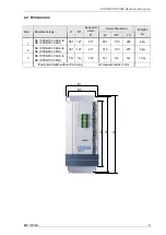
BU1100 GB
Up to 16 different addresses can be selected via the servo controller DIP switches, these addresses are
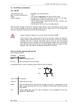
only read in when the power supply for the servo controller is switched on. Terminating resistors are
integrated and can be set or switched on like the address pre-selection via the DIP switches. These
switches are located under the opened plastic cover on the front panel of the servo controller. The
quadruple DIP switch (S1) sets the address pre-selection and the twin DIP switch (S2) enables/disables
the terminating resistor.
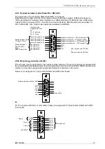
S1
S2
Arrangement of DIP switches on the servo controller, all switches are by default in the "OFF" position.
S1
Switch 4
Switch 3
Switch 2
Switch 1
Set value
CAN node
address
OFF
OFF
OFF
OFF
0
1
OFF
OFF
OFF
ON
1
2
OFF
OFF
ON
OFF
2
3
OFF
OFF
ON
ON
3
4
OFF
ON
OFF
OFF
4
5
OFF
ON
OFF
ON
5
6
OFF
ON
ON
OFF
6
7
OFF
ON
ON
ON
7
8
ON
OFF
OFF
OFF
8
9
ON
OFF
OFF
ON
9
10
ON
OFF
ON
OFF
10
11
ON
OFF
ON
ON
11
12
ON
ON
OFF
OFF
12
13
ON
ON
OFF
ON
13
14
ON
ON
ON
OFF
14
15
ON
ON
ON
ON
15
16
Address settings for the bus on the quadruple DIP switch
The addresses for CAN nodes are increased by 1 in the servo controller, i.e., when 0 is set as an
address with the DIP switch, the servo controller will have the CAN node address “1”.
The baud rate can be set to 10K, 20k, 50k, 125k, 250k, 500kBaud and 1MBaud. The default rate is
500kBaud, an optional variant is available with 1MBaud. The settings are made via the supplied NORD
SERV operating software.
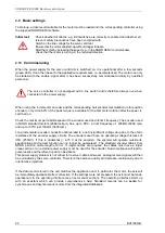
S2
Switch 1
Switch 2
Function
ON
---
Terminating resistor for RS 485 switched on with 120
Ω
---
ON
Terminating resistor for CAN bus switched on with 120
Ω
Function of twin DIP switch
O
O
1
1


