


NORDAC SK 1000E Hardware description
BU1100 GB
15
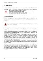
2.5.5 RS 232 and RS 485 (X4)
The RS 232 interface enables the NORDAC SK 1000E servo controller to be easily connected to a PC
with a serial interface and the supplied NORD SERV parameterisation and operating software. The
connected servo controller can be controlled and parameterised via this interface. This permits a
function test of the servo controller. Following parameterisation, the data record can be stored as a file
both on the PC and in the servo controller.
The RS485 interface enables up to 16 servo controllers to be connected in parallel if a converter is
used which is also available from NORD on request NORD also offers corresponding ready to use RS
483 cables (see accessories). Operation of several servo controllers via the RS485 bus requires that
the same baud rate is used by all of the units and a different address is set on each unit. The
terminating resistor integrated in the servo controller must also be connected to the end of the bus.
This is explained in the following “Can bus” section.
RS232 and RS485 pin assignment, 9 pole SUB-D female with UMC/ inch thread
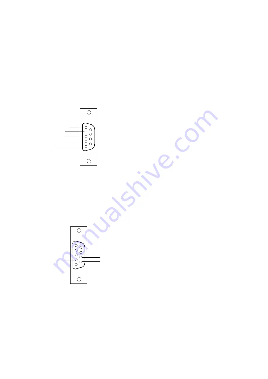
2.5.6 CAN Bus (X3)
The CAN bus interface is compatible with the ISO 11898 standard. The pin assignment of the SUB-D
connector is compatible with the CANopen standard.
Pin assignment, 9 pole SUB-D male with UMC/ inch thread
The use of an external CAN bus nodal connector with 2 screw terminal connections is recommended
(see Accessories chapter).
The CAN bus is electrically isolated from the power supply and coupled with the terminal grounds
RS485
High
GND
RS232 Rx
RS232 Tx
6
1
5 9
RS485 Low
GND
CAN_L
6
1
5 9
GND
CAN_H


