


NORDAC SK 1000E Hardware description
BU1100 GB
11
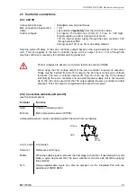
2.4
Line and motor connections
WARNING
THIS EQUIPMENT MUST BE EARTHED.
Safe operation of the equipment presupposes that qualified personnel mount and operate it
in compliance with the instructions provided in these operating instructions.
In particular, the general and regional mounting and safety regulations for work on high
voltage systems (e.g. VDE) must be complied with as must the regulations concerning
professional use of tools and the use of personal protection equipment.
Dangerous voltages can be present at the line input and the motor connection terminals even
when the servo controller is switched off. Always use insulated screwdrivers on these terminal
fields!
Ensure that the input voltage source is dead before setting up or changing connections to the
unit.
Ensure that the correct supply voltage is set up for the servo controller and motor.
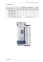
The line, motor and brake resistor connections are located on the base of the unit. They can be
accessed from the front by removing the plastic cover. All covers must be put back in place before
switching on the supply voltage!
In general, the line, motor and brake resistor cables are connected first as their terminals are located
on the bottom circuit board. The cable inlet gland is the slit opening on the bottom enclosure grid.
The following must be noted:
1. Ensure that the power source provides the correct voltage and is set up for the required current
(see the chapter on technical data)! Ensure that suitable circuit breakers with the specified current
range are switched between the voltage source and the servo controller!
2. Connect the line voltage directly to the line terminals L
1
- L
2
- L
3
and the earth (PE)! For the cable
cross-section of each wire, refer to the chapter on technical data!
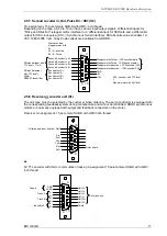
3. A four-wire shielded cable must be used to connect the motor. The cable must be connected to
the motor terminals U - V - W and the PE.
It is urgently recommended that the ready to use
motor cables from NORD are used
. They are described in the NORD cable documentation.
4. The cable shield must be applied to as much surface as possible on the shield support angle with
the supplied clamps. The clamps are also used as a strain relief.
Note:
The use of shielded cables is essential in order to maintain the specified noise suppression
level.
5. The motor cables can have a
total length of maximum 20 m
.
6. The switching cycle, the time between switching the mains on/off, must be greater than
1 minute
due to the integrated intermediate circuit capacitor charge. At least one minute must pass before
the unit can be switched back on again!
7. The optional brake resistor must also be shielded when connected. When using the NORD
substructure resistors, the cables are so short that shielding is not required.


