32
8.5
Valve Block Mounting
Ensure that no hydraulic components will interfere with any sprayer parts or be
pulled tight at any time.
The recommended mounting location is on the rear of the boom main section
near the Hardi valve block.
1.
A suitable mounting location for the valve block is illustrated in
Figure 34
.
2.
Insert the threaded rod into the block and use a hex nut to hold the rod. The block holes
are 3/8” NC-1” deep. If bolts are used instead of the threaded rod, ensure the bolts thread
in at least 3/8”.
3.
Use the remaining hardware to secure the block to the sprayer.
4.
Cut off excess threaded rod, if necessary.
Figure 34: Valve Block Mounting
Содержание UC4.5
Страница 1: ...Hardi Aftermarket New Navigator New Commander Installation Manual HD7 HD12 ...
Страница 6: ...3 3 Kit Parts 3 1 Kit Overview Figure 2 HD7 System Parts ...
Страница 7: ...4 3 2 Hydraulic Plumbing Figure 3 Single Acting Force Boom Hydraulic Plumbing ...
Страница 8: ...5 Figure 4 Double Acting Eagle Boom Hydraulic Plumbing ...
Страница 22: ...19 Figure 17 Roll Sensors Mounted on an SPC Eagle Boom ...
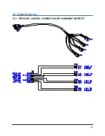
Страница 37: ...34 10 Cable Drawings 10 1 ITEM C03 44656D CABLE VALVE VARIABLE RATE DT ...
Страница 38: ...35 10 2 ITEM C05 43210 20 CABLE UC5 NETWORK 18 AWG 20M ...
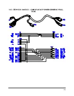
Страница 39: ...36 10 3 ITEM C10 44650 51 CABLE UC4 5 POWER GENERIC PULL TYPE ...
Страница 40: ...37 10 4 ITEM C11 44651 50 CABLE UC4 5 EXTENSION VALVE GENERIC ...
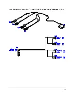
Страница 41: ...38 10 5 ITEM C12 44658 42 CABLE UC4 INTERFACE AMP ML ONLY ...
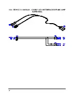
Страница 42: ...39 10 6 ITEM C13 44658 60 CABLE UC4 INTERFACE BYPASS AMP SUPERSEAL ...
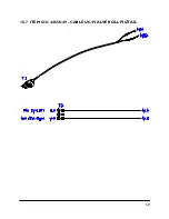
Страница 43: ...40 10 7 ITEM C16 44658 49 CABLE UC4 VALVE ROLL PIGTAIL ...
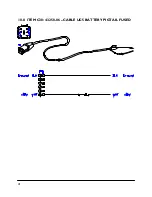
Страница 44: ...41 10 8 ITEM C30 43250 06 CABLE UC5 BATTERY PIGTAIL FUSED ...


