Nokia RH-3 Series, Устранение неисправностей - РЧ
Серия Nokia RH-3 предлагает пользовательские руководства по устранению неполадок и работе с радиочастотой (RF). Вы можете бесплатно скачать нужное руководство на нашем сайте. Наслаждайтесь удобством и качеством продукта Nokia RH-3, используя нашу бесплатную услугу загрузки.
Поделиться
Скачать


Отзывы:
Нет отзывов
Похожие инструкции для RH-3 Series
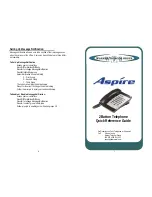
Aspire
Бренд: Warner Telecom Group Страницы: 4

CHARM
Бренд: Icemobile Страницы: 59

hiptop
Бренд: T-Mobile Страницы: 4

007SH
Бренд: SoftBank Страницы: 124

T-Mobile 4044W
Бренд: Alcatel Страницы: 24

C62G
Бренд: Dinstar Страницы: 8

GQ3039
Бренд: Ulefone Страницы: 32

4013M
Бренд: Alcatel Страницы: 44

UNIVERGE SV8100 DT7 SERIES
Бренд: NEC Страницы: 16

one touch Fire 4012X
Бренд: Alcatel Страницы: 31

Style F-02A
Бренд: Docomo Страницы: 469

SS990
Бренд: M4 Страницы: 22

Dialog 4422
Бренд: Aastra Страницы: 117

IN610
Бренд: InFocus Страницы: 120

UC840(P)
Бренд: Hanlong Страницы: 2

3902
Бренд: Avaya Страницы: 11

A1402SII
Бренд: AU Страницы: 86

ADR910L
Бренд: Pantech Страницы: 213


