5
Connecting PMC Network Interface Cards
76
Nokia IP1200 Series Security Platform Installation Guide
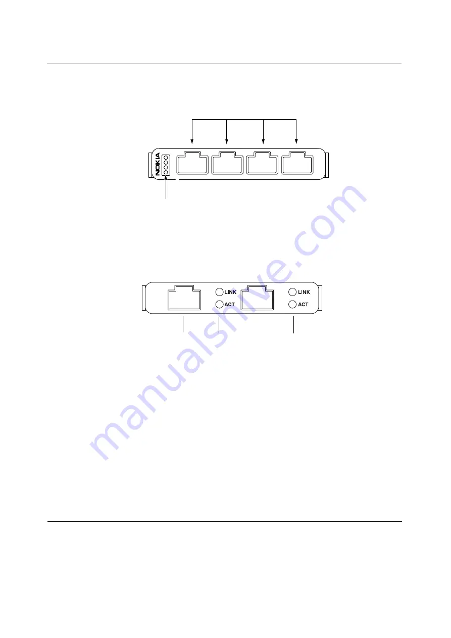
Figure 12 Four-Port 10/100 Ethernet NIC Front Panel Details
Figure 13 Dual-Port 10/100 Ethernet NIC Front Panel Details
After the power is turned on and the cables are connected, the Ethernet link
LEDs on both the IP1200 Series and on the remote equipment illuminate to
indicate the connection. As data is transmitted, the activity LEDs on the
appliance illuminate.
00026
3
2
1
1
2
3
4
4
Activity LED (blinking green)
Link LED (solid green)
Ports
RJ-45 connectors
00258
NOKIA
10/100
RJ-45 connectors
Link LEDs (green)
Activity LEDs (yellow)
Port 1 (P1)
Port 2 (P2)
Содержание IP1200 Series
Страница 1: ...Nokia IP1200 Series Security Platform Installation Guide Part No N450897003 Rev B Published May 2004 ...
Страница 4: ...4 Nokia IP1200 Series Security Platform Installation Guide ...
Страница 10: ...10 Nokia IP1200 Series Security Platform Installation Guide ...
Страница 14: ...14 Nokia IP1200 Series Security Platform Installation Guide ...
Страница 38: ...1 Overview 38 Nokia IP1200 Series Security Platform Installation Guide ...
Страница 52: ...2 Performing the Initial Configuration 52 Nokia IP1200 Series Security Platform Installation Guide ...
Страница 72: ...4 Installing and Replacing Network Interface Cards 72 Nokia IP1200 Series Security Platform Installation Guide ...
Страница 118: ...7 Troubleshooting 118 Nokia IP1200 Series Security Platform Installation Guide ...


