OPERATION
14
Speed Scrub
t
2601 Cylindrical Brush (12–02)
4.
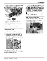
To adjust scrub head, slightly loosen the (4) lock
nuts on the roller mounting bracket and the jam
nut on the scrub head leveling knob (Figure 23).
Turn knob clockwise to lower rear of scrub head
and counter–clockwise to lower front. 13mm
socket wrench required.
LOCK NUT
LEVELING
KNOB
FIG. 23
5.
After adjustment is made retighten nuts and
recheck brush pattern. Readjust if necessary.
TO ADJUST BRUSH WITH TAPERED PATTERN:
1.
Raise scrub head off floor and turn machine off.
FOR SAFETY: Before leaving or servicing
machine, stop on level surface and turn off
machine.
2.
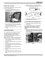
Remove the idler plate from scrub head by
releasing latches on top of scrub head (Figure 24).
FIG. 24
3.
Remove plate from end of brush.
4.
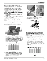
Hold idler hub shaft with 3/8” wrench and loosen
Allen head screw with 6 mm Allen wrench
(Figure 25).
FIG. 25
5.
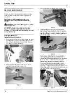
When adjusting front brush, turn shaft clockwise to
lower brush end. If adjusting rear brush, turn shaft
counter–clockwise to lower brush end. Retighten
Allen screw after adjusting (Figure 26).
FIG. 26
6.
Replace idler plate and recheck brush pattern.
Readjust if necessary.
CHARGING BATTERIES
To prolong the battery life, ONLY recharge the
batteries if discharged more than 15% of the battery
capacity. When discharged 15% or less, continue to
use the machine before recharging.
Run Time Example: 15% discharge X 3 hours rated
total run time (with maximum brush pressure) = 27
minutes.
The following charging instructions are intended
for chargers supplied with machine.
Use a charger with the following specifications to
prevent battery damage.
BATTERY CHARGER SPECIFICATIONS:
S
OUTPUT VOLTAGE - 24 VOLTS
S
OUTPUT CURRENT - 25 AMPS
S
AUTOMATIC SHUTOFF CIRCUIT
S
FOR DEEP CYCLE BATTERY CHARGING


