background image


17 

12 

Inspect and lubricate the steering bearing if necessary 


13 

Inspect and lubricate the pivot points if necessary   


14 

Lubricate the grease nipples 


Electrical system 

15 

Inspect the electric wiring for damage 


16 

Check the electric connections and terminals 


17 

Test the Emergency switch function 


18 

Check the electric drive motor for noise and damages 


19 

Test the display 


20 

Check, if correct fuses are used 


21 

Test the warning signal 


22 

Check the contactor(s)   


23 

Check the frame leakage (insulation test) 


24 

Check function and mechanical wear of the accelerator 


25 

Check the electrical system of the drive motor 


Braking system 

26 

Check brake performance, if necessary replace the brake disc or adjust the air gap 


Battery 

27 

Check the battery voltage 


28 

Clean and grease the terminals and check for corrosion and damage 


29 

Check the battery housing for damages 


Charger 

30 

Check the main power cable for damages 


31 

Check the start-up protection during charging 


Function 

32 

Check the horn function 


33 

Check the air gap of the electromagnetic brake 


34 

Test the emergency braking 


35 

Test the reverse and regenerative braking 


36 

Test the safety (belly) button function 


37 

Check the steering function 


38 

Check the lifting and lowering function 


39 

Check the tiller arm switch function 


General 

40 

Check if all decals are legible and complete 


41 

Inspect the castors, adjust the height or replace these if worn out. 


42 

Carry out a test run 


b. Lubricating points 

Lubricate the marked points according to the maintenance checklist.   

The required grease specification is: DIN 51825, standard grease. 


Содержание PTE15-C

Страница 1: ...E Please check the designation of your present type at the last page of this document as well as on the ID plate Keep for future reference Service Hotline 4008 836115 Version 10 2020 PTE15 C SPTE15 C...

Страница 2: ...and electronics will have a negative effect on the environment or health if handled incorrectly The waste packages should be sorted and put into solid dustbins according to the materials and be colle...

Страница 3: ...ning 9 b Lifting transportation 9 c Decommissioning 10 5 DAILY INSPECTION 10 6 OPERATING INSTRUCTIONS 11 a Parking 11 b Lifting 11 c Lowering 12 d Travelling 12 e Steering 13 f Braking 13 g Malfunctio...

Страница 4: ...0 Lux Modification No modifications or alterations to this pallet truck which may affect for example capacity stability or safety requirements of the truck shall be made without the prior written appr...

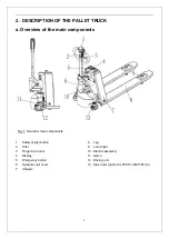
Страница 5: ...ponents 1 Safety belly button 2 Tiller 3 Finger tip control 4 Display 5 Emergency button 6 Hydraulic unit cover 7 Chassis 8 Leg 9 Load roller 10 Electric assembly 11 Apron 12 Driving unit 13 Side roll...

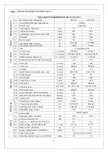
Страница 6: ...5 b Main technical data Fig 2 Technical data...

Страница 7: ...Height of tiller in drive position min max h14 mm 680 1190 680 1190 4 15 Height lowered h13 mm 80 80 4 19 Overall length l1 mm 1595 1595 4 20 Length to face of forks l2 mm 445 445 4 21 Overall width...

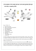
Страница 8: ...e failsafe electromagnetic brake when it is pressed By turn this button clockwise the truck can be operated after the controller checked the functions Before operating press button on display 4 to act...

Страница 9: ...evenly on the forks Use the truck with unstable unbalanced not stable load Use truck without manufacturer s written consent Lifted loads could become unstable at wind forces In the case of wind force...

Страница 10: ...ruck Check if are all parts included and not damaged Make sure the tiller is assembled correctly electrical socket is connected and fixed with two plastic clamps circlip of the axle is installed Check...

Страница 11: ...For final decommissioning hand the truck to a designated recycling company Oil batteries and electric components must be recycled due to legal regulations 5 DAILY INSPECTION This chapter describes pr...

Страница 12: ...correct assembling Check the presence of warning stickers and signs section 2c and section 12 6 OPERATING INSTRUCTIONS BEFORE OPERATING THIS TRUCK PLEASE FOLLOW THE WARNINGS AND SAFETY INSTRUCTIONS CH...

Страница 13: ...lling TRAVEL ON INCLINES ONLY WITH THE LOAD FACING UPHILL DO NOT TRAVEL ON INCLINES MORE THAN SPECIFIED WITH THE TECHNICAL DATA After starting the truck by activation from Pin code panel move the till...

Страница 14: ...ectly to the opposite direction the truck brakes regenerative until it starts traveling into the opposite direction The truck brakes if the tiller is moved up or down to the braking zones B If the til...

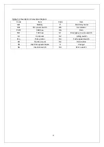
Страница 15: ...or installing changing the batteries Before finishing the maintenance work make sure that all cables are connected correctly and that there are no disturbing towards other components of the truck Tabl...

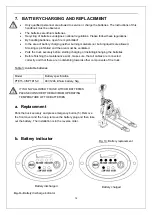
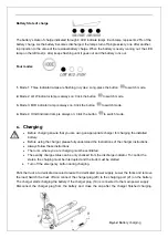
Страница 16: ...itch mode c Charging Before charging ensure that you are using an appropriate charger for charging the installed battery Before using the charger please fully understand the instructions of the charge...

Страница 17: ...nal spare parts Please consider that oil leakage of hydraulic fluid can cause failures and accidents It is allowed to adjust the pressure valve only from trained service technicians Check the items em...

Страница 18: ...or adjust the air gap Battery 27 Check the battery voltage 28 Clean and grease the terminals and check for corrosion and damage 29 Check the battery housing for damages Charger 30 Check the main powe...

Страница 19: ...5 C 0 2 L Waste material like oil used batteries or other must be probably disposed and recycled according to the national regulations and if necessary brought to a recycling company The oil level in...

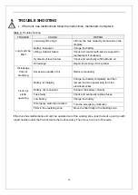
Страница 20: ...inder Oil leakage from air breathing Excessive quantity of oil Reduce oil quantity Truck not starts operating Battery is charging Charge the battery completely and then remove the main power plug form...

Страница 21: ...20 10 WIRING CIRCUIT DIAGRAM a Electrical circuit diagram PTE15 C Electrical lifting Fig 16 Electric diagram FU 1 10A FU 01 30A...

Страница 22: ...tricity meter SM DC power switch BE Accelerator FU01 30A fuse HA Horn FU1 10A fuse S1 Emergency reverse switch Et Controller S2 Lifting switch Mp Pump motor S3 Turtle speed switch Mt Traction motor S4...

Страница 23: ...22 SPTE15 C Manual lifting Fig 17 Electric diagram FU1 10A FU01 30A...

Страница 24: ...GB Battery SA Interlock switch SM DC power switch P Electricity meter FU01 30A fuse BE Accelerator FU1 10A fuse HA Horn Et Controller S1 Emergency reverse switch Mp Pump motor S3 Turtle speed switch M...

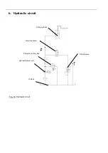
Страница 25: ...b Hydraulic circuit Fig 18 Hydraulic circuit Lifting cylinder Lowering valve e Pressure control valve Throttle valve Hydraulic power unit Oil tank...

Отзывы: