Single Digit Nixie Tube Clock ‘Z566’
www.pvelectronics.co.uk
- 14 -
4.8.2
Testing the power supplies
Use the GND, 5V and ‘170V’ test points to test first the 5V
supply, then the 160V supply. Adjust the position of VR1 until
the voltage is 160V. 160V is normally sufficient for good tube
brightness. You can adjust the voltage up to the full 170V later
if you want the tube to be brighter. When all is in order,
disconnect the power supply. Take care, as the output capacitor
can still hold charge at 160V after the supply is disconnected.
Before proceeding with the rest of the PCB assembly, it is a
good idea to de-solder the power input cable, as it can get in
the way when soldering the remaining components.
4.9
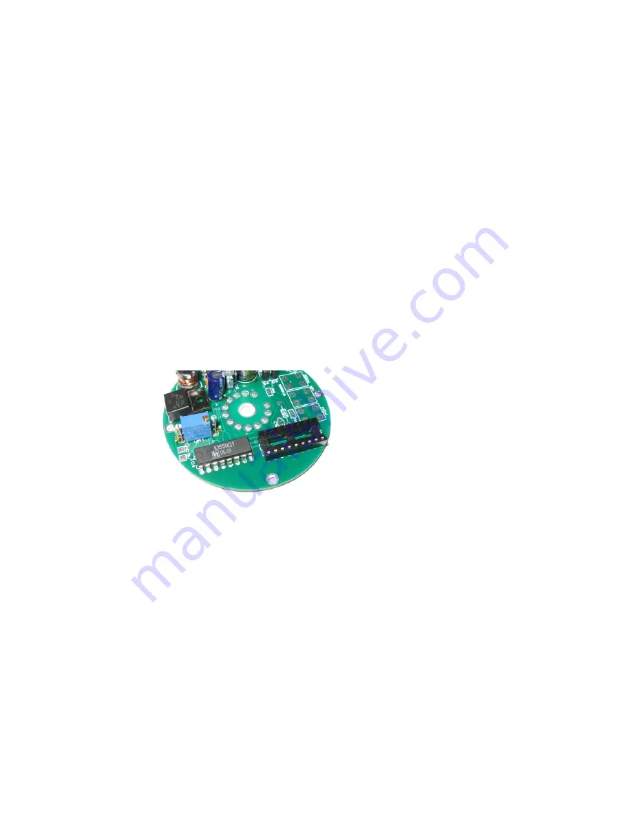
Socket for IC3, IC4
Insert the 18 Way IC socket into the PCB, ensuring that the notch
at one end is aligned with the corresponding mark on the PCB.
Insert IC4 directly into the PCB. Solder both components in place,
but do NOT insert IC3 at this stage. This will be inserted at the
very end of the assembly.
4.10
R3, R4, C6, D6,
R3 and R4 should be placed vertically. The lead pitch of C6 may not
match exactly the pitch of the holes on the PCB. If so, bend the
leads sufficiently to insert the component. D6 needs to be placed
the correct way round, so ensure the black band on the component
body aligns with the band on the PCB marking.
4.11 1mm Nixie tube sockets.
There are 11 individual 1mm sockets to solder in. The following is a
convenient way to install the sockets:
Place all the sockets, then place a flat object over the top of the
sockets to keep them from falling and invert the PCB to solder the
sockets in place. A third hand, from a helper, is most useful at this
stage!
Figure 15: IC4 and
the socket for IC3


