


Technical Instruction
Ex-Separator Module iXT0
Certificates and approvals
page 38
Ex-Separator Module iXT0 - rev. 02 / 28.08.2017
Certificates and approvals
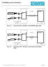
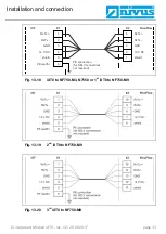
This technical description uses the designations X1 (to transmitter) or X2 (to sen-
sors) for the terminal clamps according to chapter “13.2 Wiring diagram”.
For the EC type examination certificate the internal electrical diagrams of the iXT0
modules have been filed. These diagrams use the designations X2, X3, X4, X5
and X6 for the externally accessible terminal strips.
This is why in the EC type examination certificate the latter references are quoted
instead of the designations used in this technical description.
Allocation of connections:
−
First line - designation of the function according to chapter 13.2
−
Second line (TB) - respective clamp no. on the iXT0
−
Third line (BMP) - designation as used in the following EC type examination
certificate
Transmitter connection (non-Ex-area):
Rx/Tx +
Rx/Tx -
GND
12 V DC
shield
PE (earth)
TB:
X1. 1
X1. 2
X1. 3
X1. 4
X1. 5
X1. 6
BMP:
X2, 1
X2, 2
X2, 3
X2, 4
X2, 5
X2, 6
Sensor connection for plugs S1, S2, S3 and S4 (Ex-area, zone 1):
S1
mA 1 +
mA 1 -
shield
S1 PWR +
GND-Ex
S1 Rx/Tx -
S1 Rx/Tx +
TB:
X2.1
X2.2
X2.3
X2.4
X2.5
X2.6
X2.7
BMP:
X4, 7
X4, 6
X4, 5
X4, 4
X4, 3
X4, 2
X4, 1
S2
shield
S2 PWR +
GND-Ex
S2 Rx/Tx -
S2
R
x
/T
x
+
TB:
X2.8
X2.9
X2.10
X2.11
X2.12
BMP:
X3, 5
X3, 4
X3, 3
X3, 2
X3, 1
S3
mA 2 +
mA 2 -
shield
S3 PWR +
GND-Ex
S3 Rx/Tx -
S3 Rx/Tx +
TB:
X2.13
X2.14
X2.15
X2.16
X2.17
X2.18
X2.19
BMP:
X6, 7
X6, 6
X6, 5
X6, 4
X6, 3
X6, 2
X6, 1
S4
shield
S4 PWR +
GND-Ex
S4 Rx/Tx -
S4 Rx/Tx +
TB:
X2.20
X2.21
X2.22
X2.23
X2.24
BMP:
X5, 5
X5, 4
X5, 3
X5, 2
X5, 1


