Nivetec AquaSensors AV88 Скачать руководство пользователя страница 54


Thermo Scientific AquaSensors

 AV88 Universal Analyzer User Guide


52


9.


RELAY MENUS 


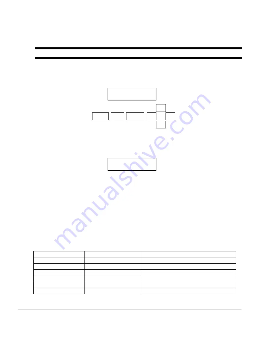
Up to two Form C relays with normally open and normally closed contacts are available with the AV88.  When 
relay A is energized or activated, an “A” will appear in the upper right corner of the measure display.  If relay B 

is energized a “B” will appear as shown: 


The selectable features in the relay menus are the same regardless of the type of personality module installed 

in the AV88.  While the AV88 is being used to calibrate the sensor, the relay is held in its present state. Use the 

UP/DOWN arrows to scroll the relay option list.  Press ENTER to select.  Press ESC to move up a level in the 
menu system. 


The SET FUNCTION menu is used to configure a relay for ALARM, CONTROL or WASH functions.  When 

ALARM is selected, the relay activation is determined by low and high limits of the chosen measured 

parameter.  When CONTROL is selected, the relay activation is determined by a single set point.  WASH is a 
timer function and does not depend on the sensor or temperature measurements.  


First select the desired relay function: ALARM, CONTROL or WASH.     


Next, select the PARAMETER (Sensor or Temperature) that drives the relay if either Alarm or Control 

is selected.  If Wash is selected, the relay operates as a timer.   


If ALARM is selected, the following activation options can be programmed in the ACTIVATION menu. 

ALARM Function 

Edit Range 

Default Setting 

Set Low Alarm 

Min to Max scale 

Zero or most negative reading 

Set High Alarm 

Min to Max scale 

Highest reading 

Set Low Deadband 

0 to 14 pH 

0 pH 

Set High Deadband 

0 to 14 pH  

0 pH 

Set Off-Delay 

0 to 999 seconds 

0 seconds 

Set On-Delay 

0 to 999 seconds 

0 seconds 


If CONTROL is selected, the following activation options can be programmed in the ACTIVATION menu. 

Relay A 
Set Function 

Set Parameter 
Set Activation 
Exit 

991.3 

S/cm       AB 

 30.8 °C        

MENU 

ESC 

ENTER 


Содержание AquaSensors AV88

Страница 1: ...Thermo Scientific AquaSensors AV88 Universal Analyzer and Controller User Guide...

Страница 2: ...LPcheck GLPdoc ISEasy KAP LabConnect LogR Low Maintenance Triode Minimum Stir Requirement MSR NISS One Touch One Touch Calibration One Touch Measurement Optimum Results Orion Star Pentrode pHuture MMS...

Страница 3: ...anual is subject to change without notice as improvements are made and does not represent any commitment whatsoever on the part of Thermo Fisher Scientific Thermo Fisher Scientific cannot accept any r...

Страница 4: ...pecified Only a skilled trained or authorized person should carry out installation setup and operation of the sensor system Before using the display make sure that the sensor cable is connected as spe...

Страница 5: ...SENSOR TYPE ALL 25 4 4 ZERO CALIBRATE MENU SENSOR TYPE CONDUCTIVITY DO TURBIDITY 28 4 5 AIR CALIBRATION SENSOR TYPE D O 30 4 6 TEMPERATURE 1 POINT SAMPLE CALIBRATION 32 5 CONFIGURE MENU 35 5 1 MAIN CO...

Страница 6: ...owed Therefore the operating instructions and specifications must be read and understood by all persons involved in installation and operation of this equipment This manual identifies safety instructi...

Страница 7: ...ing all warnings and cautions in the documentation regarding all products used in this measurement system including the sensor mounting hardware AV88 electronics and cabling Observing the prescribed e...

Страница 8: ...ions include Modbus DeviceNet RS 232 ASCII Profibus and others There are seven keys for menu navigation The MENU key provides options for calibration configuration communications outputs and relays Th...

Страница 9: ...sors AV88 Universal Analyzer User Guide 7 AV88 conduit box is mounted to a wall or plate with 8 or M4 screws through the mounting holes as shown Seven Pg11 16 Conduit breakouts are available for cord...

Страница 10: ...Panel Mount A DIN panel mount bezel and gasket can be ordered to fit the AV88 as shown The AV88 display is tightened down to the bezel using the four captured screws in the AV88 The bezel is then moun...

Страница 11: ...2 2 3 DIN Panel Mount The AV88 Display can be mounted directly to a DIN panel opening using the captive mounting screws in the AV88 and the DIN supports as illustrated in the figure below A DIN bezel...

Страница 12: ...cal sensors There is a sensor personality module for each sensor type that is plugged in and fastened down as shown if figure 2 1A Sensor personality modules show which sensor the AV88 is configured f...

Страница 13: ...d as shown in Figure 2 1B Be sure to keep the acorn nut in a safe place so that a new module can be properly secured Insertion Hold the personality module by the push pull rod Insert the guidepost thr...

Страница 14: ...Plus sensor by installing the appropriate personality module Each module clearly shows how to wire the sensor with terminal numbers wire colors and sensor functions Current parameters include pH ORP C...

Страница 15: ...ace is shown in Figure 2 2 It consists of an LCD module that contains two lines of 16 alphanumeric characters and seven keys to navigate the menu The contrast of the LCD module can be adjusted by simu...

Страница 16: ...e top line indicate the state of the relays when this option is installed An uppercase letter indicates that the corresponding relay is energized An underscore indicates that the corresponding relay i...

Страница 17: ...ser is to provide input The right arrow symbol on the screen indicates that downward navigation through the menu structure is possible The left arrow symbol on the screen indicates that upward navigat...

Страница 18: ...w will be used to move to the Calibrate menu Main Menu Analog Output 1 MENU ESC ENTER Main Menu Configure MENU ESC ENTER Main Menu Calibrate MENU ESC ENTER Select CALIBRATE with the ENTER key To calib...

Страница 19: ...Control or Wash functions if installed Press the DOWN ARROW for next selection Main Menu Relay B MENU ESC ENTER Select RELAY B with the ENTER key To set up Relay B for Alarm Control or Wash functions...

Страница 20: ...AB show that both Relay A and Relay B are energized Main Menu Exit MENU ESC ENTER Select EXIT with the ENTER key Return to the measure screen Press an UP ARROW to review the menu Press ESC for Measur...

Страница 21: ...ading to calculated reading of oxygen in air with pressure and salinity configuration settings as well as temperature reading Assumes sensor is placed in air Dissolved Oxygen Temperature 1 Point Set m...

Страница 22: ...2 Figure 4 2 The complete calibrate menu for D O sensor For the Conductivity and Turbidity sensors calibration options are 1 Point Sample Zero and Temperature as shown in Figure 4 3 ORP sensors have o...

Страница 23: ...cally updated during this step as shown in Figure 4 4 Figure 4 4 Sensor value is dynamically updated It is best to let the sensor value stabilize in the buffer solution before initiating the calibrati...

Страница 24: ...alibration of the second point After the second calibration point has been stored the user is prompted to confirm a successful calibration procedure When the ENTER key is pressed to acknowledge that t...

Страница 25: ...is shown on the screen When the ENTER key is pressed the calibrate menu is displayed The analog output remains in hold mode This ends the 2 point buffer calibration procedure The user has the option...

Страница 26: ...s completed After the calibration procedure has been aborted the user is prompted to confirm the abort When the ENTER key is pressed the analog output is placed into the active mode and the monitoring...

Страница 27: ...lowed for any sensor type Only the units of measure and span will change Press MENU from the Measure Screen Scroll to CALIBRATE with the UP DOWN Arrows and press ENTER Scroll the list of CALIBRATE opt...

Страница 28: ...edure as shown in Figure 4 6 When the reading has stabilized press ENTER to initiate the calibration Figure 4 6 Dynamic display of the sensor value during calibration When the user presses enter the c...

Страница 29: ...in Figure 4 8 Figure 4 8 Entering the calibration value After the calibration process is complete the user is asked to confirm the result before releasing the current outputs relays and measure screen...

Страница 30: ...O calibration Press ENTER to select Figure 4 9 The complete zero menu for conductivity Be sure conductivity sensors are dry and suspended away from objects that could affect the measurement in air Pre...

Страница 31: ...essing ENTER to confirm Calibration is okay the Measure screen will be displayed If an error occurs during calibration the reason for the failure is shown Press ENTER to acknowledge the calibration fa...

Страница 32: ...on procedure is initiated the analog output is placed into hold mode The user is prompted to place the sensor in air as shown in the Figure 4 12 Figure 4 12 The user is prompted to place the sensor in...

Страница 33: ...analog output is placed into active mode and the monitoring of sensor and temperature values is resumed This successfully completes the air calibration procedure If an error occurs during calibration...

Страница 34: ...s the ENTER key from the TEMPERATURE calibration menu to initiate the calibration process When the temperature calibration procedure is started the analog output is placed into hold mode The user is p...

Страница 35: ...calibration value is presented for editing When the value has been edited as desired the enter key is pressed and the calibration of the point is started During this time the calibration procedure can...

Страница 36: ...bration procedure If an error occurs during calibration that causes the procedure to fail the reason for the failure will be shown When the ENTER key is pressed the calibrate menu is displayed This en...

Страница 37: ...ds Set zero seconds for no filter Set up to 100 seconds for time to reach 90 of final value 1 to 5 seconds should be optimal for most applications The temperature filter value should generally be set...

Страница 38: ...vel menus for conductivity pH DO and Turbidity are shown below The complete configure menu for Conductivity is shown in Figure 5 1 Figure 5 1 The complete configure menu for conductivity The complete...

Страница 39: ...the sensor filter configuration is viewed and set The gray key is pressed to move to the next screen This sequence is an example for all configuration menus From the Measure Screen Press the MENU key...

Страница 40: ...and DOWN arrow keys to change the number in parentheses to the desired sensor filter in seconds Press the ENTER key to keep the filter setting currently in parentheses Or press the ESC key to leave t...

Страница 41: ...e screen with the ESC key When finished with MENU functions return to the Main Configure screen with the ESC key Observe the response time of the measurement The temperature filter should also be chan...

Страница 42: ...o 10 points If the table has fewer than 10 points the last point in the table must be set to 0 S cm and 0 Thus a typical table with four points will have the form shown in Table 1 Table 1 A typical co...

Страница 43: ...able 2 Record the table values here before entering them Point Conductivity X Coordinate S cm Concentration Y Coordinate 1 2 3 4 5 6 7 8 9 10 Entering the Concentration Table The concentration table e...

Страница 44: ...read the conductivity coordinate for the first point is shown To view the corresponding concentration coordinate press the RIGHT arrow key To view the second point in the table press the DOWN arrow k...

Страница 45: ...nt and at a higher rate These keys provide a fine adjustment The RIGHT and LEFT arrow keys increment and decrement respectively the value by a large amount Pressing and holding the RIGHT or LEFT arrow...

Страница 46: ...rious keys for the viewing and editing modes is shown in Table 3 Table 3 Summary of key actions Mode Action Press Scroll X and Y LEFT and RIGHT arrow Scroll point UP and DOWN arrow Edit coordinate ent...

Страница 47: ...entration table is shown in Table 4 Table 4 The default concentration table Point Conductivity X Coordinate S cm Concentration Y Coordinate 1 0 0 2 20 000 99 99 3 0 0 4 0 0 5 0 0 6 0 0 7 0 0 8 0 0 9 0...

Страница 48: ...e AV88 is being used to calibrate the sensor the analog output is held at its present value The analog output menu is used to scale the analog output in the AV88 The following selections are available...

Страница 49: ...s Use the ENTER key to configure the Analog Output of choice In this example Analog Output 1 is shown Use the UP DOWN arrows to scroll through the Analog Output configuration options of Set 4 mA Value...

Страница 50: ...DOWN arrow keys Press ENTER to accept the value in parentheses Press ESC to leave the value unchanged 7 2 Calibrating Output Current To make adjustments to the 4 mA and 20 mA values find the CALIBRAT...

Страница 51: ...N arrows to display the 20 mA Point Select with the ENTER key The ammeter should read exactly 20 00 mA If not adjust the value displayed on the meter using the AV88 UP DOWN arrow keys The number displ...

Страница 52: ...o not change Set Setpoint 0 to 14 pH 7 pH Set Proportional Gain 99 99 to 99 99 0 00 is direct action is reverse action Set Integral Gain 0 00 to 50 00 reps min 0 00 reps min Set Derivative Gain 0 00 t...

Страница 53: ...99 99 0 00 is direct action is reverse action Set Integral Gain 0 00 to 50 00 reps min 0 00 reps min Set Derivative Gain 0 00 to 10 00 seconds 0 00 seconds Set Transit TimeError Bookmark not defined...

Страница 54: ...low and high limits of the chosen measured parameter When CONTROL is selected the relay activation is determined by a single set point WASH is a timer function and does not depend on the sensor or tem...

Страница 55: ...RELAY B 3 Press ENTER to select the desired relay 4 Scroll with the UP DOWN arrows to view FUNCTION 5 Press ENTER to select Function and use the UP DOWN arrows to select Alarm Control or Wash 6 Press...

Страница 56: ...version of the AV88 Enter the Menu with the MENU key Scroll the menu options with the UP DOWN arrows The Help menu is second to last Press ENTER to select the HELP menu Press ENTER again to select the...

Страница 57: ...or installation 2 Damage caused by any repair or attempted repair not authorized by Thermo Fisher Scientific 3 Any product not used in accordance with the instructions furnished by Thermo Fisher Scien...

Страница 58: ...ot valid unless accepted in writing Sales taxes shall be included on the invoice unless a valid tax exemption certificate is supplied Return Material Authorization Contact Thermo Fisher Scientific Cus...

Страница 59: ......

Страница 60: ...258476 001 Rev A 01 09...

Отзывы: