Nilfisk-Advance Convertamatic 260B Скачать руководство пользователя страница 1

8/93 revised 12/00  Form Number 56043021
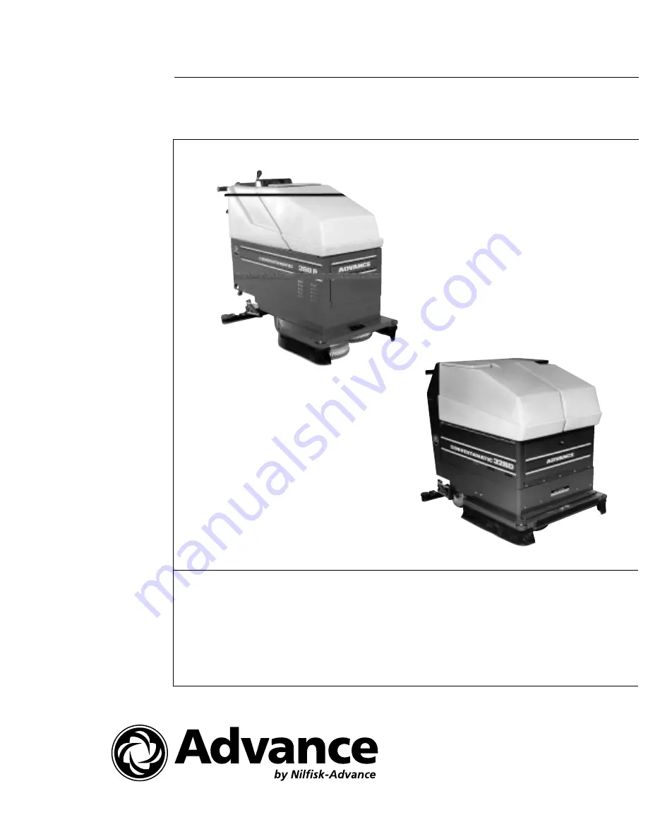
Convertamatic

 260B/32B/32BD/38BD

SERVICE MANUAL

Advance MODELS 56372450(260B), 56395700(32B)
56395710(32BD), 56395720(38BD)
56372460(260BHD), 56395715(320BHD), 56395725(380BHD)

Hydro-Retriever

 260BHD/320BHD/380BHD

Содержание Convertamatic 260B

Страница 1: ...orm Number 56043021 Convertamatic 260B 32B 32BD 38BD SERVICE MANUAL Advance MODELS 56372450 260B 56395700 32B 56395710 32BD 56395720 38BD 56372460 260BHD 56395715 320BHD 56395725 380BHD Hydro Retriever 260BHD 320BHD 380BHD ...

Страница 2: ...38 320 380 19 Brush Drive Motor Replacement 32 38 320 380 22 Brush Drive Motor Replacement 260 20 Brush Drive System Maintenance 14 Brush Drive System Troubleshooting 31 Caster Replacement 51 Differential Removal 32BD 38BD 320BHD 380BHD 49 Drive Belt Removal 32BD 38BD 320BHD 380BHD 45 Drive System Maintenance 45 Drive System Troubleshooting 32BD 38BD 320BHD 380BHD 52 Drive Wheel Removal 32BD 38BD ...

Страница 3: ...Vacuum Motor Carbon Brush Inspection 32 38 320 380 35 Vacuum Motor Carbon Brush Inspection 260 33 Vacuum Motor Removal 32 38 320 380 38 Vacuum Motor Removal 260 36 Vacuum System Maintenance 32 Vacuum System Troubleshooting 44 Note All references to right left front or rear in this manual are as seen from the operator s stand point TABLE OF CONTENTS _________________________________________________...

Страница 4: ..._______________________________________________________________________________________________________________________________________________________________________________________________________________________________________________________________________ GENERAL SAFETY INSTRUCTIONS Specific Cautions and Warnings are included to warn you of potential danger of machine damage or bodily harm...

Страница 5: ...ry Use caution when moving the machine in below freezing temperature conditions Any water in the solution or recovery tanks or in the hose lines could freeze Do not leave the machine unattended without first turning the Main Switch OFF and applying the Parking Brake if applicable Turn the Main Switch OFF before changing the brushes __________________________________________________________________...

Страница 6: ...w o batteries 702 lbs 318 kg w 220 AH batteries 733 lbs 332 kg w 244 AH batteries Battery Weight 65 lbs 30 kg each 220 AH battery 73 lbs 33 kg each 244 AH battery Battery Dimensions Height 10 63 inches 27 cm each 220 AH battery Width 7 06 inches 18 cm each 220 AH battery Length 10 25 inches 26 cm each 220 AH battery Height 11 5 inches 29 cm each 244 AH battery Width 7 06 inches 18 cm each 244 AH b...

Страница 7: ...Recovery Tank Capacity 28 gal 106 litre Machine Weight 569 lbs 258 kg w o batteries 32B 627 lbs 284 kg w o batteries 32BD 320BHD 641 lbs 290 kg w o batteries 38BD 380BHD 1018 lbs 462 kg w batteries 32B 1076 lbs 488 kg w batteries 32BD 320BHD 1090 lbs 494 kg w batteries 38BD 380BHD Battery Weight 73 lbs 33 kg each 244 AH battery Battery Dimensions Height 11 5 inches 29 cm each 244 AH battery Width ...

Страница 8: ...lean Vacuum Shut Off Float Clean Squeegee Charge Batteries Check Battery Water Level Lubrication Grease Lubrication Oil Service Vacuum Motor Lubricate these items every month with grease 1 2 pressure arm bearings 2 2 main wheel bearings 260 32B 3 4 differential bearings 2 intermediate shaft bearings 32BD 38BD 320BHD 380BHD 4 Caster swivel and wheel bearings if applicable Lubricate these items ever...

Страница 9: ...32 38 320 380 6 The solution filter is flushed when ever the solution tank is drained through the drain hose 260 ________________________________________________________________________________________________________________________________________________________________________________________________________________________________________________________________________ SOLUTION VALVE REPLACE...

Страница 10: ...___________________________________________________________________________________________________________________________________________________________________________________________________________________________ SOLUTION VALVE REPLACEMENT 260 continued A E Front E D C B D 7 Solution Filter ...

Страница 11: ...e solution valve 2 Remove the right side skirt and the right side brush 3 See Figure 2 Disconnect the 2 F solution hoses 4 Remove the 2 G screws holding the valve bracket to the chassis 5 Pull the solution valve down and disconnect solution cable H from the valve arm do not loose the bushing 6 Disconnect main solution hose I and remove the solution valve from the machine 7 Remove the old solution ...

Страница 12: ..._______________________________________________________________________________________________________________________________________________________________________________________________________________________ SOLUTION VALVE REPLACEMENT 32 38 320 380 continued FIGURE 2 I Front G F H F 9 ...

Страница 13: ...p the solution tank forward and remove the recovery tank from the machine 3 Remove the vacuum motor hose for easier access 4 See Figure 3 Disconnect solution cable J from the solution valve arm 5 Remove the solution cable from the chassis mount take note of its location in the mount 6 Remove the control handle panel 7 Remove the solution cable from the handle mount take note of its location in the...

Страница 14: ...s Mount ________________________________________________________________________________________________________________________________________________________________________________________________________________________________________________________________________ SOLUTION CABLE REPLACEMENT 260 continued 11 ...

Страница 15: ...____________________________________________ SOLUTION CABLE REPLACEMENT 32 38 320 380 1 Drain the solution and recovery tanks 2 Remove the right side skirt and right side brush Lower the brush drive 3 See Figure 4 Disconnect the 2 K solution hoses 12 4 Remove the 2 L screws holding the valve bracket to the chassis 5 Pull the solution valve down and disconnect solution cable M from the valve arm do...

Страница 16: ...__ Problem Not Enough Solution Flow To The Scrub Brushes 1 Kinked solution hoses 2 Solution valve cable needs adjustment 3 Plugged screen in the solution tank 32 38 320 380 4 Plugged solution filter 260 see figure 1 ________________________________________________________________________________________________________________________________________________________________________________________...

Страница 17: ...ox and check the oil level The oil should be 1 1 2 inches 3 8 cm from the top of the gear box Use 140W gear lube only ________________________________________________________________________________________________________________________________________________________________________________________________________________________________________________________________________ BRUSH DRIVE BELT ...

Страница 18: ...________________________________________________________________________________________________________________________________________________________________________________________________________________________________________ BRUSH DRIVE BELT ADJUSTMENT 260 continued FIGURE 1 ...

Страница 19: ...JUSTMENT 32 38 320 380 FIGURE 2 1 Drain the solution and recovery tanks and tip them to the sides of the machine 2 Open the front access door 3 See Figure 2 Loosen the 2 C bolts 4 Remove the belt guard 5 Turn the 2 large D bolts an equal amount of turns each to loosen or tighten the belt If you are removing the belt loosen the tension and remove the belt 6 There should be about 3 32 inch 2 mm of b...

Страница 20: ..._____________________________________________________________________________________________________________________________________________________________ BRUSH DRIVE MOTOR CARBON BRUSH INSPECTION 260 1 Drain and remove the solution and recovery tanks and disconnect the batteries 2 See Figure 3 Remove access panel E from under the solution tank FIGURE 3 ...

Страница 21: ...H DRIVE MOTOR CARBON BRUSH INSPECTION 260 continued FIGURE 4 3 See Figure 4 Remove the F brush covers from the brush drive motor 4 Remove one of the brushes from its holder 5 Measure the length of the brush If it is worn to a length of 3 8 inch 10 mm or less remove the brush motor see the BRUSH DRIVE MOTOR REPLACEMENT section of this chapter and replace all of the brushes If it is longer than 3 8 ...

Страница 22: ...and tip them to the sides of the machine FIGURE 5 2 Disconnect the batteries 3 See Figure 5 Remove belt guard G 4 Remove large equalizer spring H 5 Remove bracket I 6 Remove the J brush covers from the brush drive motor 7 Remove one of the brushes from its holder 8 Measure the length of the brush If it is worn to a length of 3 8 inch 10 mm or less remove the brush motor see the BRUSH DRIVE MOTOR R...

Страница 23: ...__________________________________________________________________________________________________________ BRUSH DRIVE MOTOR REPLACEMENT 260 1 Drain and remove the solution and recovery tanks and disconnect the batteries 2 See Figure 3 Remove access panel E from under the solution tank 3 Disconnect the brush drive motor wires take note of their location for reassembly 4 See Figure 6 Remove large e...

Страница 24: ...brush drive motor 8 Reassemble in reverse order and test for proper operation FIGURE 6 ________________________________________________________________________________________________________________________________________________________________________________________________________________________________________________________________________ BRUSH DRIVE MOTOR REPLACEMENT 260 continued ...

Страница 25: ...________________________________________________________________________________________________________ BRUSH DRIVE MOTOR REPLACEMENT 32 38 320 380 1 Drain the solution and recovery tanks and tip them to the sides of the machine 2 Disconnect the batteries and open the front access door 3 See Figure 7 Remove panel O 4 Disconnect the brush drive motor wires take note of their location for reassembl...

Страница 26: ...________________________________ BRUSH DRIVE MOTOR REPLACEMENT 32 38 320 380 continued FIGURE 8 5 See Figure 8 Remove the 2 P bolts and remove the belt guard 6 Remove large equalizer spring Q 7 Remove bracket R 8 Turn the 2 large S bolts to loosen the belt tension and remove the belt 9 Remove bolt T and remove the brush drive motor from the machine 10 Remove the 4 U bolts and nuts and remove the m...

Страница 27: ...s springs and washers 6 Disconnect the solution hoses from the X tubes 7 Remove the Y bolts and lift the pressure arm assemblies out of the machine 8 Remove the Z nuts 9 Use blocks of wood to support the brush holder OO and drive the pressure arm shaft PP out of the brush holder and pressure arm QQ Note Hold a brass drift against the pressure arm shaft and hammer on the drift Hammering directly on...

Страница 28: ...______________________________________________________________________________________________________________________________________________________________________________________________________________________________________________ PRESSURE ARM BEARING REPLACEMENT 260 continued ...

Страница 29: ...2 CC bolts springs and washers 7 Disconnect the solution hoses from the DD tubes 8 Remove the EE bolts and lift the pressure arm assemblies out of the machine 9 Remove the FF nuts 10 Use blocks of wood to support the brush holder RR and drive the pressure arm shaft SS out of the brush holder and pressure arm TT Note Hold a brass drift against the pressure arm shaft and hammer on the drift Hammerin...

Страница 30: ...________________________________________________________________________________________________________________________________________________________________________________________________________________________________ PRESSURE ARM BEARING REPLACEMENT 32 38 320 380 continued FIGURE 10 ...

Страница 31: ...alling the pad holders on the machine 2 Push the control handle lock down to hold the handle in the neutral position and lower the brush drive to the floor 3 See Figure 11 Loosen lock nut HH 4 Turn the main power switch ON and start the brush drive motor The machine should not move forward or reverse with the handle locked in the neutral position 5 If it does turn propelling adjustment shaft II to...

Страница 32: ...____________________ PROPELLING LINKAGE ADJUSTMENT 32 38 320 380 1 Put the brushes or pad holders on the machine Make sure that they are the proper size and type for the machine If pad holders are being used install proper size pads before installing the pad holders on the machine 2 See Figure 12 Disconnect spring JJ take note of its location for reassembly this step is for drive models only 3 Low...

Страница 33: ... Test run the machine to make sure it does not move in any direction when locked in neutral When testing move the machine around to different locations to make sure an uneven floor surface is not causing it to move 9 See the TROUBLESHOOTING section of this chapter if the machine does not propel properly FIGURE 13 _____________________________________________________________________________________...

Страница 34: ..._____________________________________________________________________________________________________________________________________________________________________________________________________________________________________________ Problem Squealing Noise When Brushes Are Lowered 1 Brush drive belt needs adjustment _____________________________________________________________________________...

Страница 35: ...squeegee tool 2 Replace the squeegee blades if they are nicked or torn 3 If the edge of the squeegee blade is worn to a radius turn it around or over so a new edge faces forward 4 Inspect the squeegee hose rinse any built up dirt from the hose Replace the hose if it is kinked or damaged 5 Clean the float ball cage 6 Check the recovery tank cover gasket to make sure it seals 7 Check the drain hose ...

Страница 36: ...__________________________________________________________________________________________________________________________________________________________ VACUUM MOTOR CARBON BRUSH INSPECTION 260 1 Drain the solution and recovery tanks and remove them from the machine 2 Disconnect the batteries 3 See Figure 1 Remove access panel A 33 FIGURE 1 A Front ...

Страница 37: ...the brush Replace both brushes if it is 3 8 inch 10 mm or shorter 8 Reassemble in reverse order and test for proper operation ________________________________________________________________________________________________________________________________________________________________________________________________________________________________________________________________________ VACUUM MO...

Страница 38: ...ecovery tanks and tip them to the sides of the machine 2 Disconnect the batteries and open the front access door 3 Remove the large equalizer spring take note of which hole it is hooked in before removing 4 See Figure 3 Remove access panel C FIGURE 3 35 5 Remove plastic cover D from the end of one of the vacuum motors 6 Remove one of the brush holders and remove the carbon brush from the motor 7 M...

Страница 39: ..._________________________________________________________________________________________________________________________________________ VACUUM MOTOR REMOVAL 260 1 Drain the solution and recovery tanks and remove them from the machine 2 Disconnect the batteries 3 See Figure 4 Remove access panel E 4 Unplug the vacuum motor from the wiring harness 36 Front E FIGURE 4 ...

Страница 40: ... and test for proper operation ________________________________________________________________________________________________________________________________________________________________________________________________________________________________________________________________________ VACUUM MOTOR REMOVAL 260 continued 37 FIGURE 5 Front F F F ...

Страница 41: ...AL 32 38 320 380 1 Drain the solution and recovery tanks and tip them to the sides of the machine 2 Disconnect the batteries and open the front access door 3 Remove the large equalizer spring take note of which hole it is hooked in before removing 4 See Figure 6 Remove access panel G FIGURE 6 G H Front 5 Disconnect the vacuum motor s that you are removing from the wiring harness 6 Remove the 3 H s...

Страница 42: ...lades if they are cut nicked or wavy 3 Put the squeegee back on the machine and put the squeegee lever in the down position 4 See Figure 7 Turn the I screws to set the squeegee angle so that the front and rear blades touch the floor equally Alternate between the screws making small adjustments one turn or less at each one 39 5 If the front blade is off the floor loosen the top screws and tighten t...

Страница 43: ... blade is worn to a radius turn it around or over so that a new edge is facing forward 3 Put the squeegee back on the machine and put the squeegee lever in the down position 4 See Figure 8 Turn the J screws to set the squeegee angle so that the entire length of the wiping blade sits flat on the floor Alternate between the screws making small adjustments one turn or less at each one FIGURE 8 5 If t...

Страница 44: ..._________________________________________________________________________________________________________________________________________________________________ SQUEEGEE BLADE REPLACEMENT STRAIGHT 1 To disassemble the squeegee cartridge remove the 2 small K screws and 2 large L screws see Figure 9 41 FIGURE 9 K K L L O M N Wood Support Blocks ...

Страница 45: ... 2 large L screws to draw all parts securely together 8 Remove one L screw and install a small K screw in its place then repeat this step with the other L screw _______________________________________________________________________________________________________________________________________________________________________________________________________________________________________________...

Страница 46: ...__________________ SQUEEGEE BLADE REPLACEMENT CURVED 1 Remove the squeegee tool assembly and disassemble it 2 Discard the worn blade s and thoroughly wash the remaining parts 3 Install the new blade s and reassemble as shown in Figure 11 4 Make sure that the screws or nuts are not so tight that the blades are wavy or bent out of shape 5 Reinstall the squeegee on the machine and test for proper ope...

Страница 47: ..._______________________________________________________________________________________________________________________________________________________ Problem Water In Vacuum Motor 1 Operator using a high sudsing detergent 2 Drain hose plug not sealing 3 Vacuum shut off float not closing ______________________________________________________________________________________________________________...

Страница 48: ...shaft bearings and the caster swivel and wheel bearings once per month 2 Lubricate the drive chain every 3 months ________________________________________________________________________________________________________________________________________________________________________________________________________________________________________________________________________ DRIVE BELT REMOVAL 32...

Страница 49: ...shes lower the brush drive assembly open the left splash guard and front access door 6 Remove bolt D and lower the idler pulley assembly to the floor Be careful not to loose the bushing and washers around bolt D 7 Remove bracket E from the top of the gear box 8 Remove bolt F pull belt guard G toward the rear and work belt H off of lower pulley I 9 Work the belt off of idler pulley J off of upper p...

Страница 50: ... of the wheels 3 Reassemble in reverse order and test for proper operation ________________________________________________________________________________________________________________________________________________________________________________________________________________________________________________________________________ MAIN WHEEL REMOVAL 260 1 Drain and remove the solution and r...

Страница 51: ...on ________________________________________________________________________________________________________________________________________________________________________________________________________________________________________________________________________ MAIN WHEEL REMOVAL 32B 1 Drain the solution and recovery tanks remove all of the battery cables remove the batteries and tip the mac...

Страница 52: ..._________________________________ DIFFERENTIAL REMOVAL 32BD 38BD 320BHD 380BHD 1 Drain the solution and recovery tanks remove all of the battery cables remove the batteries and tip the machine on its left side 2 Remove the master link from the drive chain and remove the chain from the machine 3 See Figure 4 Remove the P bolts holding squeegee centering assembly Q in place and remove the centering ...

Страница 53: ... file or a wire brush and loosen the Z set screws see Figure 5 ________________________________________________________________________________________________________________________________________________________________________________________________________________________________________________________________________ DIFFERENTIAL REMOVAL 32BD 38BD 320BHD 380BHD continued 7 Collar AA must ...

Страница 54: ...________________________________________________________________________________________________________________________________________________________________________________________ CASTER REPLACEMENT The caster wheel is located on the back of the 260 and on the front of the 32 38 320 380 The bearings in the swivel portion of the caster seldom fail The bearings in the caster wheel are usually d...

Страница 55: ...20BHD 380BHD Before troubleshooting the transport drive system make sure the brake is OFF ________________________________________________________________________________________________________________________________________________________________________________________________________________________________________________________________________ Problem No Wheel Drive But Brush Motor Runs 1...

Страница 56: ..._______________________________________________ BATTERY MAINTENANCE Proper maintenance of electric vehicle batteries can greatly extend their life There are 3 simple rules for good battery maintenance Maintain Proper Electrolyte Level Use distilled water in batteries whenever possible If batteries are discharged add just enough water to cover the plates in each cell If batteries are fully charged ...

Страница 57: ... or more cell that is putting out less voltage than the other cells Note Always charge batteries before testing There are 2 ways to find a dead cell Use a hydrometer to check the specific gravity or state of charge of the fluid in each cell A dead cell is one that reads 50 points or more lower than the other cells Use a volt meter to check the voltage of each battery with the brush and vac motors ...

Страница 58: ...Nilfisk Advance Inc 14600 21st Avenue North Plymouth MN 55447 3408 www nilfisk advance com Phone 800 989 2235 Fax 800 989 6566 2001 Nilfisk Advance Inc Plymouth MN 55447 3408 Printed in the U S A ...

Отзывы: