WHEEL DRIVE SYSTEM
________________________________________________________________________________________________________________________________________________________________________________________________________________________________________________________________________
DRIVE MOTOR REPLACEMENT
1
Drain the tanks, remove the batteries and tip the machine up on it’s nose.
2
Disconnect the squeegee lift cable and the squeegee hose.
3
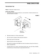
See Figure 1. Remove chain guard "K" (snaps in place).
4
Loosen lock nut “J” and turn bolt “A’ to loosen the chain tension (On reassembly, refer to the
Drive Chain
Adjustment
section for proper chain tensioning).
5
Disconnect the master link on the chain and remove the chain.
6
Disconnect the drive motor from the wiring harness.
7
Remove the (2) “I” bolts and nuts and remove the drive motor from the machine.
8
Remove the old drive motor from the motor mount and install the new motor on the mount.
9
Remove the chain guard “H” from the old motor and install it on the new one.
10
Follow steps 1-6 in reverse order to reassemble.
11
Test the drive system for proper operation.
________________________________________________________________________________________________________________________________________________________________________________________________________________________________________________________________________
DRIVE CHAIN REPLACEMENT OR ADJUSTMENT
________________________________________________________________________________________________________________________________________________________________________________________________________________________________________________________________________
Replacement:
•
Refer to steps 1, 3 & 4 of the
Drive Motor Replacement
section for instructions. Follow these steps in
reverse order to reassemble.
________________________________________________________________________________________________________________________________________________________________________________________________________________________________________________________________________
Adjustment:
•
See Figure 1. Loosen the lock nut “J”, turn bolt “A” to tighten or loosen the chain. There should be about
1/2 inch (12 mm) of deflection between the sprockets when moderate pressure is applied to the chain.
•
After replacing or adjusting the chain, test the drive system for proper operation.
17
BA 500
Service Manual

