


Electrical System
80
Service Manual – SC6500
™
Wiring Diagram Tips
Wiring diagrams show how electrical components are connected together and to a large degree “how things
work”. They do not show where things are located. Here are some tips when using these diagrams.
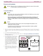
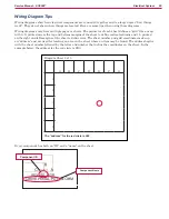
Wiring diagrams may have multiple pages or sheets. The perimeter of each sheet defines a “grid” like a map;
with A-G printed across the top and bottom margins of the sheet to define vertical columns and 1-5 printed
on the right and left margins of the sheet to define rows. The sheet number and grid coordinates make up
an “address” and are used for locating an area on the sheet where an item may be found. The address begins
with the sheet number followed by the letter and number that define the coordinates on the sheet. In the
example below, the address for the red circle is 2E3.
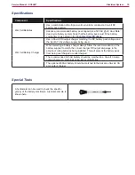
Every component has both an “ID” and a “name” on the sheet.
Component ID
Component Name
A
B
C
D
E
F
G
1
2
3
4
5
The “address” for the red circle is 2E3
Diagram Sheet 2 of 3
Содержание 56414010
Страница 32: ...Chassis System 32 Service Manual SC6500 Chassis System Major Chassis Components 45 in 48in 1300mm models only ...
Страница 87: ...Options and Accessories 87 Service Manual SC6500 Description Warning Beacon Back Up Alarm Overhead Guard ...
Страница 138: ...Scrub System Disc 138 Service Manual SC6500 Special Tools Actuator Power Cord Adapter p n 56407502 ...
Страница 175: ...Sweep System Side Broom 175 Service Manual SC6500 Special Tools Actuator Power Cord Adapter p n 56407502 ...