


Solution System
141
Service Manual – SC6500
™
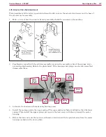
Detergent Tank and Pumps
The
Detergent Pumps
pump detergent from the
Detergent Tank
to the tee fitting upstream of the solution
pump. The
Detergent Pumps
get PWM voltage from the A2 Control Board to regulate the speed of the
Detergent Pumps
and the subsequent detergent flow.
Solution System Wiring Diagram
Circuit Description
Solution System
The
Solution Control Pump M12
and solution
Solenoid Valve L1
get positive voltage from the
Battery
when the
load side of contactor
K5
is closed. The contactor
K5
closes when the
A2 Control Board Assembly
connects the
K5
coil to battery ground.
A2 Control
Board
Assembly
A3
Switch/Display
Panel Assembly
Fuse, 250 A
36V Battery
A1
Speed
Controller
Motion
8
B-
B+
F4
K7
F1
+
1
2
-
S1
S2
S3
D1
Key Switch
Seat Switch
Battery Interlock Switch
(for roll-out Battery)
Diode
F2
Circuit Breaker, 15 Amp
Circuit Breaker, 3 Amp
K5
4
3
16
15
Direction
Battery Ground
CAN H
CAN L
Solution Control Pump
Solenoid Valve
Detergent Metering Pump
M12
L1
+
-
Detergent Metering Pump
+
-
S5
Solution Empty Switch
(closes when empty)
+
-
Accessory Pump
(optional)
M
M
M
M
M13
M16
M15
B+
B+
B-
Bat -
Bat -
Bat +
Bat +
Bat +
Bat -
Bat -
Bat -
+
-
Содержание 56414010
Страница 32: ...Chassis System 32 Service Manual SC6500 Chassis System Major Chassis Components 45 in 48in 1300mm models only ...
Страница 87: ...Options and Accessories 87 Service Manual SC6500 Description Warning Beacon Back Up Alarm Overhead Guard ...
Страница 138: ...Scrub System Disc 138 Service Manual SC6500 Special Tools Actuator Power Cord Adapter p n 56407502 ...
Страница 175: ...Sweep System Side Broom 175 Service Manual SC6500 Special Tools Actuator Power Cord Adapter p n 56407502 ...