Engine System
25
Service Manual – PBU Propane Floor Burnisher
When the base current is flowing, the trigger sensor (TS1) detects optimum time (peak current) to shut off
the transistor base current. With the transistor rapidly shutting off the current at the primary coil, counter-
electromotive force is generated and voltage in hundreds-volts is induced through the primary winding (L1),
thereby producing extremely high voltage at the secondary winding (L2). When this secondary voltage steps
up to k-volts, “ionization” meaning “ignition” occurs across the electrodes at the spark plug (SP).
The trigger sensor located internally in the ignition system is set to give constant ignition timing according
to engine speed and temperature.
The diode (D1) located at the ignition shut-off circuit prevents misconnection of battery voltage, protecting
the internal components of the ignition system. When the stop switch (SW) is set at the closed position,
primary voltage is routed to ground, not allowing igniting operation.
Cleaning of paper air cleaner elements is not recommended. Each air cleaner element should be replaced
with a new air cleaner element at the maintenance time as shown in the maintenance chart.
Note:
Operating in dusty condition may require more frequent maintenance than shown in the
chart above.
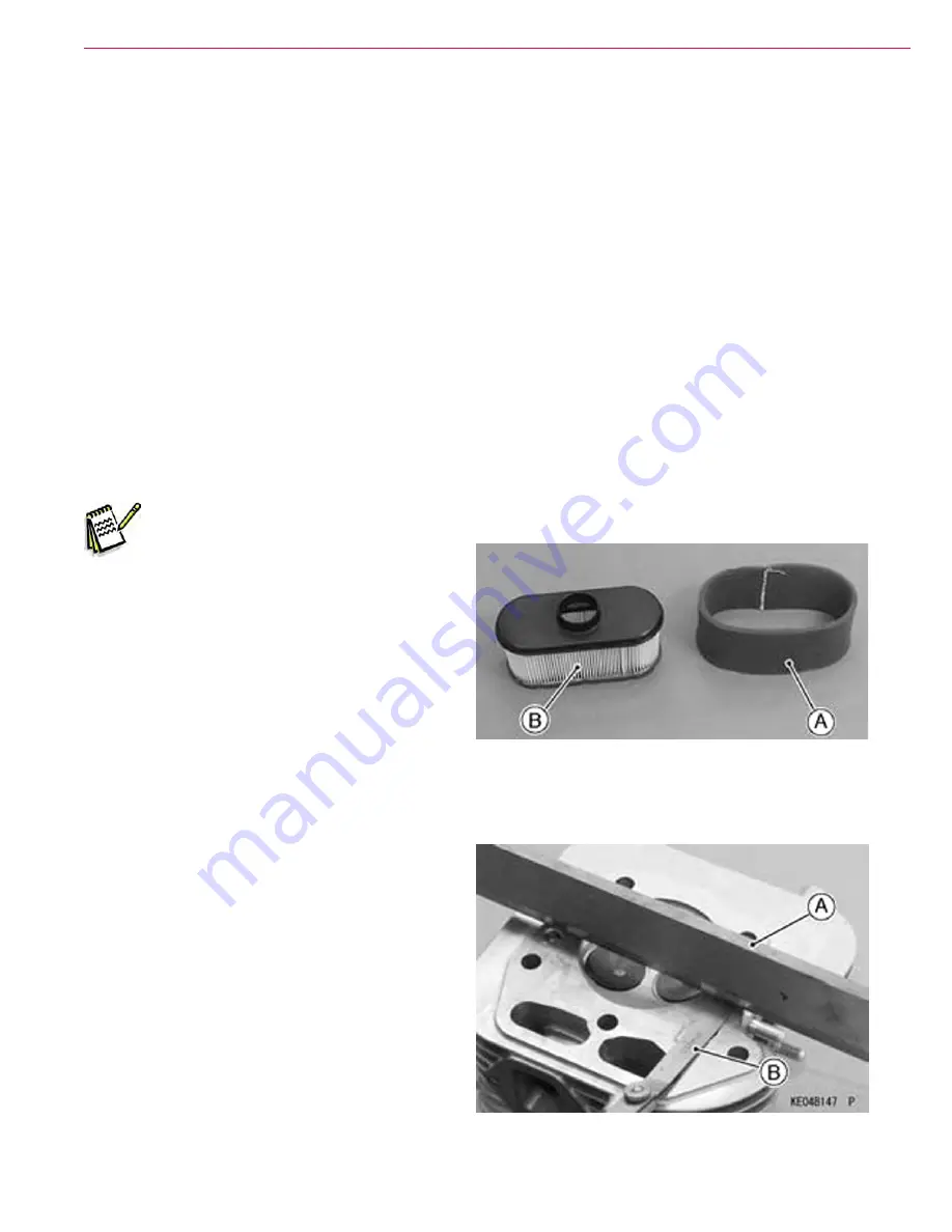
• Remove the foam and paper elements
• Clean the foam element [A] in a bath
of detergent and water, and let the
element air-dry thoroughly.
Figure 17 Air Cleaner Element
Maintenance and Adjustments
Air Cleaner Element Cleaning and Inspection
Engine Top End Cylinder Head Inspection
• Lay a straightedge [A] across the mating
surface of the head at several different points,
and measure warp by inserting a thickness
gauge [B] between the straightedge and head.
•
If warp exceeds the service limit, repair the
head by lapping the mating surface with emery
paper secured to a surface plate (first No. 200,
than No. 400). If the mating surface is badly
damaged, replace the cylinder head.
Cylinder Head Warp Service
Limit: 0.05 mm (0.002 in.)
• Check the cylinder head for cracks or other
damage.
Figure 18 Cylinder Head Inspection


