


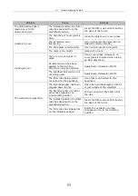

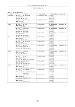
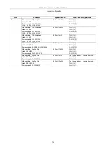
48
Shutter Control Unit Communications Commands
V
1
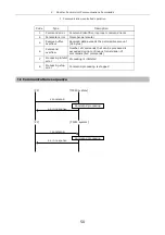
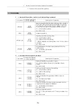
Communication-controlled operation
You can control this system from your PC or other devices through the RS-232C
interface.
Create your own control program based on the information given in this manual.
1-1
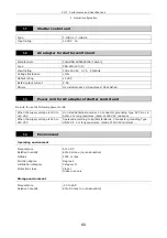
Communications system
Start-stop serial communication
1-2
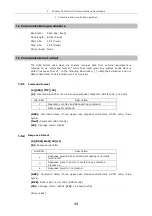
Connector specification
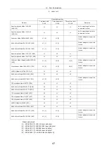
The following signals are used with the system's serial interface connector:
D-sub 9-pin connector (male)
Pin No.
Signal
I/O
1 Unused
-
2 RxD
Input
3 TxD
Output
4 Unused
-
5 GND
GND
6 Unused
-
7 Unused
-
8 Unused
-
9 Unused
-
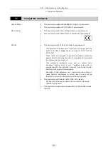
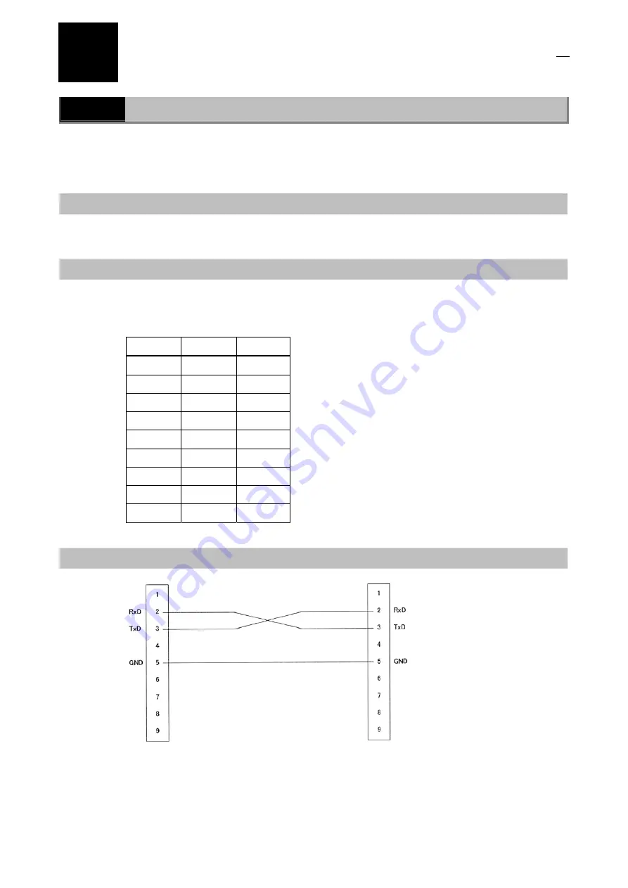
1-3
Cable specification
*
To ensure trouble-free operation, use the supplied RS-232C cable for connecting your PC.
Содержание TIRF2
Страница 1: ...TIRF2 SYSTEM FOR TE2000 INSTRUCTIONS M339E 04 12 NF 2 ...
Страница 2: ......