

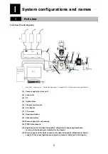
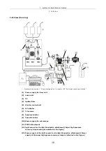

I
System configurations and names
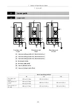
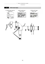
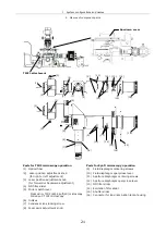
2 Laser path
11
2
Laser path
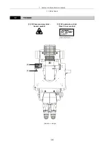
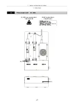
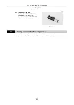
2.1
Laser unit
(1) Laser
mounting
position
L1 (See table below.)
(2) Laser
mounting
position
L2 (See table below.)
(3) Laser
mounting
position
L3 (See table below.)
(4) Motorized
shutter
(5) ND filter (ND4, ND8)
(6) Laser synthesis mirror
(7) Laser out (single-mode fiber)
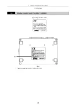
Laser
mounting
position
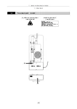
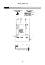
L1 L2 L3
Two-laser unit
C-LU2
405nm to 514nm
532nm to 640nm
-
Three-laser unit
C-LU3
405nm to 440nm
633nm to 640nm
488nm to 514nm
532nm to 561nm
Three-laser unit
C1-LU3
488nm to 514nm
532nm to 543nm
594nm to 633nm
(2)
(1)
(3)
(7)
(2)
(1)
(4)
(5)
(3)
(7)
(6)
(1)
(4)
(5)
(2)
(7)
(6)
Two-laser unit
C-LU2
Three-laser unit
C-LU3
Three-laser unit
C1-LU3
(4)
(5)
(6)
Содержание TIRF2
Страница 1: ...TIRF2 SYSTEM FOR TE2000 INSTRUCTIONS M339E 04 12 NF 2 ...
Страница 2: ......


