background image

Chapter 3    Names of Parts and Their Functions 

1    DS-U3 DS Camera Control Unit 

- 6 - 

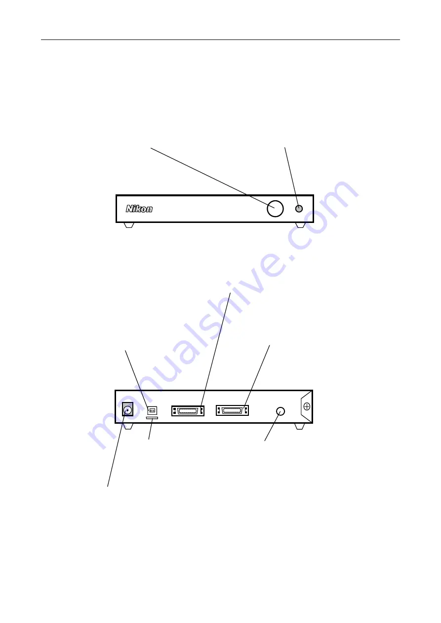
(2) Front of the DS-U3 


(3) Rear of the DS-U3


DC IN 12V  IEEE1394     CAMERA1          CAMERA2            EXT.I/O

Power switch

This is a push switch. Press to 
turn it on. Press again to release 
and turn it off. When the power is 
on, the power indicator lights up.

Power indicator

When power is turned on, the indicator 
first flashes green, and then turns to 
green. When the indicator lights up in 
green, the DS-U3 is ready for operation.

IEEE1394 connector 

Connects to a PC via an IEEE 
1394b cable.   

CAMERA 1 connector

Connects to the DS camera head. 

Be sure to turn off power before 
connecting or disconnecting the 
connector: otherwise, the equipment 
malfunctions. 

DC lN 12V connector 

Use the supplied AC adapter. 

CAMERA 2 connector 

Connects to the DS camera head. 

Be sure to turn off power before 
connecting or disconnecting the 
connector: otherwise, the equipment 
malfunctions. 

EXT. l/O connector 

When the DS-Qi1Mc is connected, 
image capture can be externally 
triggered by supplying external trigger 
signals from this port. 
(Cannot be used unless DS-Qi1Mc is 
connected.) 

Holder 

Keeps the cable from being 
pulled off the lEEE1394 
connector. 

Содержание DS-Fi1

Страница 1: ...DS U3 DS Camera Control Unit DS Camera Head DS Fi1 DS Vi1 DS Cooled Camera Head DS Qi1Mc DS Fi1c DS Ri1 Instructions Ver 1 00 M554E 10 11 NF 1 M554EN01 ...

Страница 2: ......

Страница 3: ...or incorrect please contact your nearest Nikon representative Some of the equipment described in this manual may not be included in the set you have purchased If you intend to use any other equipment with this product read the manual for that equipment too If the equipment is used in a manner not specified by the manufacturer the protection provided by the equipment may be impaired Trademarks Micr...

Страница 4: ...ction Methods 12 Chapter 5 Microscope Setting 15 Chapter 6 Operation Method 19 1 Connecting a Camera Head 19 2 Installing the DS U3 Device Driver 20 3 Installing Application Software 24 4 Operation 26 Chapter 7 Care and Maintenance 29 1 Cleaning the System 29 2 Storage 29 Chapter 8 Troubleshooting 31 1 Power Supply 31 2 Application Software Startup 32 3 Image Output to a PC Monitor 32 4 Camera Set...

Страница 5: ...operty damage To ensure correct usage read this manual carefully before using the product Do not discard this manual and keep it handy for easy reference Safety instructions in this manual are marked with the following symbols to highlight their importance For your safety always follow the instructions marked with these symbols Symbol Description Warning Disregarding instructions marked with this ...

Страница 6: ...wer cord contact your nearest Nikon representative When used in 100 120 V region outside Japan UL listed detachable power cord set 3 conductor grounding 3 conductor grounding Type SVT No 18 AWG 3 m long maximum rated at 125 V AC minimum When used in 220 240 V region Detachable power cord set approved according to EU EN standard 3 conductor grounding 3 conductor grounding Type H05VV F 3 m long maxi...

Страница 7: ... area of 100 mm or more Arrange a layout that allows easy removal of the power cord from the inlet of the AC adapter in the event of an emergency 2 Turn off the power before assembling the product or connecting disconnecting cables To prevent failure or malfunction be sure to turn off the power switch of the DS U3 before assembling the product or connecting disconnecting a cable 3 Connect only the...

Страница 8: ...Safety Precautions vi ...

Страница 9: ...lor DS Fi1 2 3 inch color 5 24 megapixel White DS Vi1 1 1 8 inch color 2 11 megapixel White DS Qi1Mc 2 3 inch monochrome 1 50 megapixel Applied Black DS Fi1c 2 3 inch color 5 24 megapixel Applied Black DS Ri1 2 3 inch color 1 50 megapixel Applied Applied Black For details of the features above refer to Chapter 9 Specifications Pixel shifting is a high resolution photographing function available by...

Страница 10: ...y items are missing contact your nearest Nikon representative immediately 1 DS U3 DS Camera Control Unit 6 Power cord 2 Vertical stand 7 DS camera cable DS Camera I F cable 20 26 3 m 3 Instruction manual 8 DS Camera Head with a C mount cap 4 NIS Elements freeware package CD ROM 9 C mount adapter optional 5 AC adapter ...

Страница 11: ...em requirements PC unit Item Requirements Type Windows PC CPU Equivalent to Xeon 2 6 GHz or higher Memory 2 GB or more Hard disc 100 MB of free hard disk space for installation 300 MB of free disk space for program execution Video 1280 x 1024 pixels High Color mode or better True Color mode recommended OS Windows 7 Windows XP Japanese English Note Use Windows 7 Professional Windows XP Professional...

Страница 12: ...otograph subjects other than photomicrographs Any lens that meets the following conditions may be used Protrudes no more than 10 mm from the mount surface into the camera Less than 5 mm for DS Ri1 The image circle of the DS Vi1 is 1 1 8 and that of the DS Fi1 DS Fi1c DS Qi1Mc or DS Ri1 is 2 3 Use a lens for 1 or 2 3 When using diaphragm settings brighter than F2 8 you may observe slight light fall...

Страница 13: ...tions 1 DS U3 DS Camera Control Unit 5 3 Names of Parts and Their Functions 1 DS U3 DS Camera Control Unit 1 External appearance of the DS U3 Ventilation hole on the top For internal cooling Ventilation hole on the left For internal cooling ...

Страница 14: ...394 connector Connects to a PC via an IEEE 1394b cable CAMERA 1 connector Connects to the DS camera head Be sure to turn off power before connecting or disconnecting the connector otherwise the equipment malfunctions DC lN 12V connector Use the supplied AC adapter CAMERA 2 connector Connects to the DS camera head Be sure to turn off power before connecting or disconnecting the connector otherwise ...

Страница 15: ...cap Protects the C mount from dusts C mount When taking microphotographs mount the C mount adapter here before connecting to the microscope When taking other photographs attach the C mount lens here CAMERA OUT connector Tripod mount Mounts the DS camera head on a tripod etc Top Bottom Rear ...

Страница 16: ...Chapter 3 Names of Parts and Their Functions 8 ...

Страница 17: ...ing and Installing the Equipment 1 Connection Diagrams 9 DS camera head DS U3 DS AC adapter Front IEEE1394b cable DS camera cable AC 4 Connecting and Installing the Equipment 1 Connection Diagrams 1 Schematic diagram PC ...

Страница 18: ...onnection Diagrams 10 Trigger signal output device Can be connected only when DS Qi1Mc is used DS AC adapter DS camera head DS camera cable PC CAMERA 2 connector CAMERA 1 connector 2 Connectors Rear of the DS U3 DC IN 12V IEEE1394 CAMERA1 CAMERA2 EXT I O ...

Страница 19: ...rtical stand to the DS U3 for setting the product in the vertical position Set the DS U3 vertically on a flat surface as shown below Provide a clearance of approximately 100 mm around the product to release heat Attach the vertical stand as follows Remove two of the four screws at the upper front position and the lower rear position on the right side of the DS U3 See Figure A below Then fix the st...

Страница 20: ...dapter If there is use an air blower or the like to wipe it out 3 Screw the C mount adapter into the C mount on the DS camera head Screw it in as far as it goes 4 Plug the C mount adapter into the vertical tube of the microscope Use the clamping screw on the vertical tube to secure the C mount adapter Likewise a relay lens can be attached The x0 7 relay lens is recommended for the DS Fi1 DS Fi1c D...

Страница 21: ...he EXT I O connector If you are connecting your own external device use a device that meets the following specifications Connector φ3 5 mm 3 pole pin jack Functions Pin 1 Exposure timing signal output HI active Pin 2 Trigger enable signal output HI active Pin 3 External trigger signal input HI active The TTL or LVTTL level signal can also be input from Pin 3 GND Pin 2 Pin 1 Pin 3 3 3 V 4 7 kΩ 100 ...

Страница 22: ...tailed instructions on triggered image capture refer to the software instruction manual 4 Connecting to a Power Supply Be sure to turn off the DS U3 before connecting the DS camera head to prevent electric shock Make all other connections before connecting to a power supply Be sure to use the specified AC adapter DS AC adapter For details refer to 3 DS AC Adapter in Chapter 9 Specifications Connec...

Страница 23: ...inserted into the illumination optical path of the microscope to compensate for changes in color balance caused by the length of exposure time When using a phase contrast microscope or an interference microscope two luminous fluxes or multiple luminous fluxes you can enhance contrast using a green interference filter GIF or a monochrome interference filter IF We recommend simultaneous use of an NC...

Страница 24: ...ng size of the aperture diaphragm Note that excessively decreasing the aperture may limit performance of the objective Terms What is depth of focus Depth of focus refers to the range along the axis of the field of view over which the image is in apparent focus Although decreasing the opening size of the aperture diaphragm extends the depth of focus the resolution will be reduced Adjust the apertur...

Страница 25: ...ffects of ambient light When capturing a dark specimen with a fluorescent microscope darken the interior lighting for photomicrography as ambient light may enter the optical path Attach the caps over the binocular eyepiece to prevent light from entering through the eyepiece 8 Effects of vibration Because photomicrography involves extremely high image resolution a slight vibration can affect image ...

Страница 26: ...Chapter 5 Microscope Setting 18 ...

Страница 27: ...sted below The control unit DS U3 mode is automatically switched by changing the camera head DS Fi1 5 megapixel CCD color non cooled DS Fi1c 5 megapixel CCD color cooled DS Vi1 2 megapixel CCD color non cooled DS Qi1Mc 1 megapixel CCD monochrome cooled DS Ri1 1 megapixel CCD color cooled pixel shift Refer to Chapter 9 Specifications for details on those cameras ...

Страница 28: ...creensaver and anti virus utility The procedure for closing the standard Windows screensaver is indicated in this manual For other programs refer to their instruction manuals Operation procedure 1 Right click on the Windows desktop to display the shortcut menu Select Personalize in the shortcut menu to open the Personalization dialog box 2 Click the Screen Saver icon in the Personalization dialog ...

Страница 29: ...s_v1 33 0_Nikon exe in the installer CD folder If the User Account Control dialog box appears click the Yes button to continue 2 When the T1394bus Driver Kit Setup dialog box appears click the Next button 3 When the dialg box to select the destination folder appears select an appropriate folder and click the Install button Click the Install button Click the Yes button Click the Next button ...

Страница 30: ...tion wizard 6 Run the following file from the installed folder for the 32 bit OS Drv installwizard 32bit t1394bus_installwizard for the 64 bit OS Drv installwizard 32bit t1394bus_installwizard 7 When the dialog box shown on the left appers select the host controller and click the Switch to T1394bus driver button Click the Next button Click the Finish button Select the host controller Click the Swi...

Страница 31: ... 8 When the Windows Security dialog box appears click the Install button 9 Check that the Driver Provider for the IEEE1394 host controller selected above has changed to Thesyoon Quit the wizard Click the Install button Check the Driver Provider for the host controller ...

Страница 32: ... and install it in the following procedures Be sure that cables to the DS U3 are connected properly and the power to the DS U3 is turned on before starting software installation Operation procedure 1 Click F Package on the installation screen 2 The Setup screen appears Click the Next button 3 The Choose Destination Location screen appears Click the Browse button when the folder for installation ne...

Страница 33: ...een appears Click the Finish button 6 Click the X button to close the window To use the Nikon NIS Elements software which is sold separately or another application dedicated to the DS U3 install it in the PC according to the instruction manual provided with each software Click the Install button Click the Finish button Click the X button Click the Select All button ...

Страница 34: ...mage window Zooming can be performed by a mouse wheel This mode changes the cursor to an interactive zoom tool that magnifies a circular part of the current image when clicked This mode enables you to insert annotation objects into pictures according to the Tools settings 2 Areas of interest This tool defines the area of the live image that is used to determine auto exposure parameters applied to ...

Страница 35: ...the bottom right corner of the image Click the arrow at the right of the button to open the pop up menu and then change the magnification of the scale 2 2 5 4 5 10 20 40 50 60 100 150 times A number of annotation objects can be inserted into the image Click the arrow at the right of the button to open the pop up menu and then select the object to be inserted from the line arrow text rectangle or c...

Страница 36: ...each software Keep the following requirements in mind when running the NIS Elements software This is because if the computer enters the Standby mode live images will not be updated after the computer wakes up Other problems may also arise Do not close the computer if it is a notebook Do not press the Sleep button on the computer Do not put the computer in Standby mode manually from an operating sy...

Страница 37: ...front of the CCD If you do touch the glass filter or if dirt cannot be removed from it contact your nearest Nikon representative and have them clean it To prevent discoloration and separation of the printing do not use organic solvents e g alcohol ether or paint thinner to clean the coated plastic or printed parts 2 Storage Turn off the power when the product is not in use Unplug the power cord wh...

Страница 38: ...Chapter 7 Care and Maintenance 30 ...

Страница 39: ...is connected Check the power plug the wall outlet the AC adapter the IEEE1394b connector and the DC IN 12 V connector of the DS U3 Check that the power cord supplied with the product is used Check that a specified AC adapter is used Check that the power switch is turned on Check that your PC has sufficient power capacity for bus powered operation The DS U3 is hot If the product is used in a hot or...

Страница 40: ...ck that the DS camera head is connected correctly Check that the C mount cap is removed from the DS camera head Check that the subject is placed within the viewfield of the microscope or the lens Check that the optical path of the microscope is in the camera side Check that the cable used is of IEEE1394 compliant For shielded twisted pair cables the cable connecting devices must be 4 5 m maximum C...

Страница 41: ...bright Check that exposure or tone is adjusted correctly using the application software Refer to the instruction manual for the application software Check that the intensity of illumination of the microscope is appropriate The color is poor Check that the white balance is set with the application software Refer to the instruction manual for the application software Check that the color compensatio...

Страница 42: ...application software Refer to the instruction manual for the application software Check that the size of the field diaphragm is adjusted so that it circumscribes the view field Check that the size of the aperture diaphragm is adjusted to approximately 70 to 80 of the numerical aperture of the objective lens Check that an appropriate filter is used When using a phase contrast microscope or an inter...

Страница 43: ...r cables the cable connecting devices must be 4 5 m maximum Check that the version of the OS is appropriate for the product The product is not compatible with the Macintosh Applicable OS Windows 7 Professional Windows XP Professional Service Pack 2 SP2 Noise is heard from the Camera Head DS Ri1 If you obtain a high resolution image by pixel shifting on DS Ri1 noise may be heard from the movable pa...

Страница 44: ...Serial No Peripheral devices connected microscope trigger signal generator etc Manufacturer s name Model Manufacturer s name Model Your PC Manufacturer s name Model Operating system OS version and Service Pack SP number Type of CPU and its clock frequency Memory capacity Types of applications and their versions NIS Elements Freeware etc Symptoms of the problem displayed messages and frequency with...

Страница 45: ...ise reduction edge enhancement horizontal vertical inversion of image Other functions Scene mode Selectable from five biological modes four industrial modes and other mode I F IEEE1394b bilingual Connect this interface to the controller PC Power supply from IEEE1394 bus power can operate one camera head connected either DS Fi1 or DS Vi1 Transfer image format IEEE1394 I F RGB 24 bit YUV411 YUV 811 ...

Страница 46: ...ixel interline CCD Color monochrome Color Infrared blocking filter Built in Max frame rate 1 5 9 fps 5M interlaced 10 0 fps 1 3M interlaced 12 0 fps 1 3M progressive scan 23 3 fps center scan 14 9 fps 2M progressive scan 27 0 fps 800 6 progressive scan 29 2 fps 800 5 progressive scan 28 8 fps center scan Number of recording pixels 2560 x 1920 1280 x 960 640 x 480 1600 x 1200 800 x 600 400 x 300 Qu...

Страница 47: ...ls 2 1280 x 1024 640 x 480 320 x 240 2560 x 1920 1280 x 960 640 x 480 1280 x 1024 640 x 512 640 x 480 320 x 256 320 x 240 4076 x 3116 pixel shifting mode 3840 x 3072 pixel shifting mode 2038 x 1558 pixel shitting mode 1920 x 1536 pixel shifting mode 1920 x 1440 pixel shifting mode 1240 x 1024 pixel shifting mode 960 x 720 pixel shifting mode 640 x 480 pixel shifting mode Quantization 12 bits Sensi...

Страница 48: ...is a high resolution photographing function available by using software on PC which is connected with IEEE1394b cable 3 DS AC Adapter Model name EA1050E 120 Manufacturer EDAC POWER Electronics Co Ltd Rated input voltage 100 to 240 VAC 50 60 Hz 1 8 A maximum Rated output voltage 12 VDC 5 3 5 A maximum External dimensions 120 L x 60 W x 35 H mm Weight 253 g Conforming standards GS CE and UL Be sure ...

Страница 49: ...ested and found to comply with the limits for a Class A digital device pursuant to Part 15 of the FCC Rules These limits are designed to provide reasonable protection against harmful interference when the equipment is operated in a commercial environment This equipment generates uses and can radiate radio frequency energy and if not installed and used in accordance with the instruction manual may ...

Отзывы: