SD64 Series
Operating & Safety Instructions
USA – 04/16
Issue 04
40
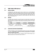
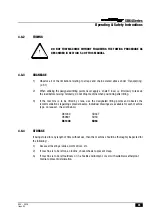
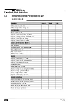
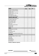
5.4.2
GEARBOX DISENGAGEMENT (TYPE 1)
The drive gearboxes located on the front and rear wheel hubs must be disengaged as follows;
1)
To disengage the gearbox, remove both screws from the cover plate, turn it upside down (as per
the diagram below), re-tighten the M5 screws to a torque of 5 Nm (3.7lbft).
2)
Before attempting to re-engage the gearbox, ensure that the machine is jacked up so the relevant
wheel is clear of the ground in order to prevent damage.
Note; Damage caused by failure to
comply with this notice will not be covered by the manufacturer’s warranty.
5.4.3
GEARBOX DISENGAGEMENT (TYPE 2)
The drive gearboxes located on the front and rear wheel hubs must be disengaged as follows;
1)
Remove both retaining bolts that secure the cover disc to the centre of the wheel hub.
2)
Partially screw one of the retaining bolts into the end of the central disengage pin and pull the pin
out fully, ensuring the recess on the pin is visible.
3)
Place the cover disc over the pin, ensuring the retaining disc is engaged in the pin recess and
secure in place using the remaining retaining bolt.
4)
To re-engage the gearbox, complete the above instructions in reverse order, ensuring gearbox
drive is free to engage before pushing the pin ‘home’. If necessary, jack up each wheel & rotate
slightly to allow re-engagement of pin.
Содержание SD64 4x4x4
Страница 2: ......
Страница 21: ...SD64 Series Operating Safety Instructions USA 04 16 Issue 04 19...
Страница 48: ......


