6
Spider
GB
F
D
E
I
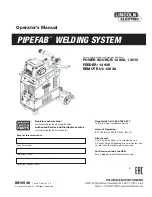
Fare uscire la staffa di
traino B di lato ed
unirla alla catena con
la vite C.
Riportare quindi
indietro la staffa B a
circa metà dei profili
(fig. 2).
Move chain support B
sideways and connect
it to the chain with
srewc C. Move support
B back about half way
along the sections
(Fig. 2).
Faire sortir l’étrier de
traction B sur le côté et
l’unir à la chaîne avec
le vis C.
Reporter ensuite l’étrier
B vers l’arrière
approximativement au
milieu du profil (fig. 2)
Den Zugbügel B
seitlich heraustreten
lassen und mit der
Schraube verbinden C.
Dann den Bügel B auf
etwa Hälfte Profil nach
hinten bringen (Abb. 2).
Haga salir el estribo de
arrastre B de costado y
únalo a la cadena con
la tornillos C.
Entonces, coloque
nuevamente hacia
atrás el estribo B,
hasta la mitad de los
perfiles (fig. 2).
GB
F
D
E
I
Unire il profilo ottenuto
allo SPIDER,
inserendolo nelle
apposite alette facendo
passare la catena oltre
il pignone del motore,
infine fissare le staffe
di sostegno D con le
viti E, piegandole a
misura (nella parte
superiore) come
indicato (fig. 3).
Nel caso in cui il profilo
oscillasse troppo,
provvedere ad un
secondo punto di
fissaggio F (fig. 3) a
circa 1 mt. dalla porta.
Join the section to the
SPIDER, slotting it in
the guides and move
the chain beyond the
motor’s pinion; lastly,
fix brackets D with
screws E, bending
them to measure (at
the top) as shown (Fig.
3). If the section moves
too much, fix it in
another point, F (Fig.
3), about 1 m from the
door.
Unir le profil obtenu au
SPIDER en
l’introduisant dans les
ailettes de guidage et
en faisant passer la
chaîne au-delà du
pignon du moteur; fixer
ensuite les pattes de
support D avec les vis
E en les pliant à la
longueur voulue (dans
la partie supérieure)
comme l’indique la fig.
3. Si le profil oscille
trop, effectuer un
second point de
fixation F (fig. 3) à
environ 1 m de la
porte.
Das so erhaltene Profil
mit dem SPIDER
vereinen und in die
dazu bestimmten
Führungen einsetzen,
wobei die Kette über
das Ritzel des Motors
hinaus geführt wird,
dann die Tragbügel D
wie in Abb. 3 gezeigt
nach Maß biegen (im
oberen Teil) und mit
den Schrauben E
befestigen. Sollte das
Profil zu stark
schwingen, einen
zweiten
Befestigungspunkt F
(Abb. 3) etwa 1 m von
der Tür entfernt
vorsehen.
Una el perfil a
SPIDER,
introduciéndolo en las
aletas de guía
correspondientes,
haciendo pasar la
cadena por el piñón del
motor; por último, fije
los estribos de sostén
(D) con los tornillos
(E), plegándolos a
medida (en la parte
superior), como
indicado en la (fig. 3).
Si el perfil oscilase
mucho, efectúe un
segundo punto de
sujeción F (fig. 3) a 1
metro aprox. de la
puerta.
2-
3-
Fig. 2
Abb. 2
Fig. 3
Abb. 3
F
1 m
D
E
B
C
Содержание SP 6060
Страница 13: ...13 Spider ...
Страница 14: ...14 Spider ...