


20
7.3.2) STOP Input
STOP is the input that causes the immediate interruption of the
manoeuvre (with a short reverse run). Devices with output featuring
normally open “NO” contacts and devices with normally closed
“NC” contacts, as well as devices with 8.2K
Ω
constant resistance
output, like sensitive edges, can be connected to this input.
During the recognition stage the control unit, like BlueBUS, recog-
nizes the type of device connected to the STOP input (see para-
graph 7.3.4 “Recognition of Other Devices”); subsequently it com-
mands a STOP whenever a change occurs in the recognized status.
Multiple devices, even of different type, can be connected to the
STOP input if suitable arrangements are made.
• Any number of NO devices can be connected to each other in
parallel.
• Any number of NC devices can be connected to each other in
series.
• Two devices with 8.2K
Ω
constant resistance output can be con-
nected in parallel; if needed, multiple devices must be connected
“in cascade” with a single 8.2K
Ω
termination resistance
• It is possible to combine Normally Open and Normally Closed by
making 2 contacts in parallel with the warning to place an
8.2K
Ω
resistance in series with the Normally Closed contact (this
also makes it possible to combine 3 devices: Normally Open, Nor-
mally Closed and 8.2K
Ω
).
If the STOP input is used to connect devices with safe-
ty functions, only the devices with 8.2K
Ω
constant resis-
tance output guarantee the fail-safe category 3 according
to EN standard 954-1.
!
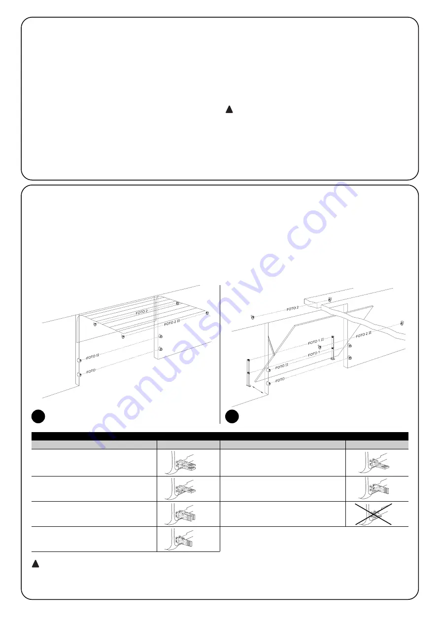
PHOTO
Photocell h=50cm
activated when door closes
PHOTO II
Photocell h=100cm
activated when door closes
PHOTO 1
Photocell h = 50
activated when door closes and opens
PHOTO 1 II
Photocell h = 100
activated when door closes and opens
FOTO 2
Photocell activated
when door opens
FOTO 2 II
Photocell activated
when door op
FOTO 3
INADMISSIBLE CONFIGURATION
7.3.3) Photocells
By means of addressing using special jumpers, the “BlueBUS” sys-
tem enables the user to make the control unit recognise the photo-
cells and assign them with a correct detection function. The
addressing operation must be done both on TX and RX (setting the
jumpers in the same way) making sure there are no other couples of
photocells with the same address. In an automation for sectional
doors or non-protruding overhead doors it is possible to install the
photocells as shown in Figure 44. In an automation with protruding
overhead doors, refer to figure 45. Photo 2 and Photo 2II are used
in special installations requiring complete protection of the automa
tion, also during opening. After the installation or removal of photo-
cells, the recognition phase in the control unit as described in Para-
graph “7.3.4 Recognition of other devices” must be carried out.
In the SN6021 versions the BlueBUS output has a maximum load of 2 units.
On SN6031 and SN6041 the maximum load is 6 units; one pair of photocells absorbs power equal to 1 BlueBUS unit.
!
44
45
Table 21: Photocell addressing
Photocell
Jumpers
Photocell
Jumpers


