GB
3
2.1) Electrical connections
Carefully follow all the connection instructions. If you
have any doubts do not make experiments but consult the
relevant technical specifications sheets which are also
available on the web site www.niceforyou.com.
An incorrect connection may cause serious damage to the
control unit. Do not connect multiple motors in parallel
unless specifically required by the type of motor; if neces-
sary, use the appropriate expansion cards.
!
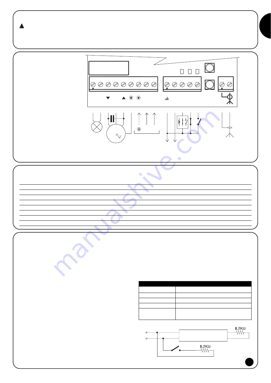
2.1.2) Description of the connections
Terminals
Function
Description
1-2
Flash
= 230V flashing light
3-4-5-6
Motor
= motor control output (close, common, open, earth)
7-8-9
Power supply
= mains power supply line (earth, phase, neutral)
10-11
24Vdc
= 24Vdc output (services) max 50mA
12
Stop
= safety device input (Stop/sensitive edge)
13
Photo
= photocell input
14
Step-by-step
= input for cyclic command (open-stop-close-stop) or TTBUS connection
15-16
Aerial
= radio receiver aerial input
F = 5A 250V
type F
T1
T2
C
L
N
+24Vcc
M
STOP
PHOTO
P.
P.
1 2 3
4 5 6 7
10 11
POWER SUPPL
Y
L
N
24 Vdc
PHOTOCELL
STEP-BY
-STEP
STOP
- +
AERIAL
2
8 9
12 13 14
FLASH
MOTOR
FLASH
15 16
2.1.1) Wiring diagram
2.1.3) Notes regarding connections
The control unit features two low voltage (24Vdc) supply terminals (10-
11) for the services (photocell). Three additional terminals (12-13-14)
are designated for the command and/or safety inputs; as for the latter,
the 0 volt terminal (10) is the common one. Some of these inputs have
functions that depend on the programmed settings.
STOP input
This input is designated for the connection of safety devices such as
sensitive edges.
The input can be used with normally closed (NC) as well as normal-
ly open (NO) contacts or constant resistance contacts (8.2K
Ω
). To
set dip-switches 3-4 based on the type of input used, refer to the
“Programmable Functions” chapter.
Warning: the minimum resistance level required by law can only be
guaranteed by the constant resistance input (dip-switch N°3=ON).
Normally the activation of the device connected to the Stop input
causes the stop of the movement with a short inversion. To deacti-
vate this inversion caused by the activation of the safety device,
when the sensitive edge touches the ground for example, a contact
“S” can be used in series with a 8.2K
Ω
resistance connected in par-
allel with the sensitive edge (see figure 2).
Contact “S” is positioned such that the last 30-40 cm of the closing
movement close before the sensitive edge activates.
When contact “S” is closed and the sensitive edge is activated by
the floor, the automation blocks without inversion keeping the door
completely closed. Only the opening operation can be performed
from this situation.
The Stop input status is signalled by the “stop” led as illustrated in
the following table.
2
LED “STOP”
STOP input status
ON
Active (allows manoeuvre)
OFF
Inactive (blocks manoeuvre)
50%ON+50%OFF
Inversion deactivated
20%ON+80%OFF
Not active with the inversion deactivated
(allows opening only)
S
12
10
Sensitive Edge
Table “A2”


