


2
– English
EN
A
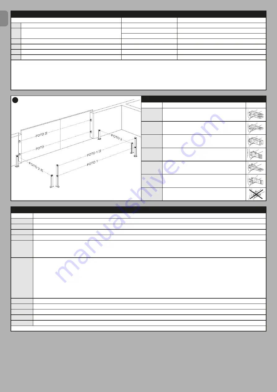
TABLE 2
-
Photocell addresses
Position
Description
Jumper
FOTO
External photocell h = 50 with trip on closure (stops and
inverts movement)
FOTO II
External photocell h = 100 with trip on closure (stops and
inverts movement)
FOTO 1
Internal photocell h = 50 with trip on closure (stops and
inverts movement) and opening (stops and restarts when
photocell is disengaged)
FOTO 1 II
Internal photocell h = 100 with trip on closure (stops and
inverts movement) and opening (stops and restarts when
photocell is disengaged)
FOTO 2
Internal photocell with trip on opening (stops and inverts
movement))
FOTO 2 II
Internal photocell with trip on opening (stops and inverts
movement)
FOTO 3
CONFIGURATION NOT ADMITTED
TABLE 1 - Technical specifications of electrical cables (fig. 2b)
Connection
Cable type
Maximum admissible length
A
CONTROL UNIT POWER cable
1 cable 3 x 1,5 mm
2
30 m (
note 1
)
B
FLASHING LIGHT with aerial cable
1 cable 2 x 0,5 mm
2
20 m
1 shielded cable type RG58
20 m (less than 5 m recommended)
C
BLUEBUS DEVICES cable
1 cable 2 x 0,5 mm
2
20 m (
note 2
)
D
KEY-OPERATED SELECTOR SWITCH cable
2 cables 2 x 0,5 mm
2
(
note 3
)
50 m
E
GEARMOTOR POWER cable
1 cable 3 x 1,5 mm
2
(
note 4
)
10 m
F
ELECTRIC LOCK CONNECTION
1 cable 2 x 1 mm
2
10 m
Note 1
– If the power cable is longer than 30 m, a cable with a larger cross-section is required (3 x 2.5 mm
2
) and safety earthing is necessary in the vicinity of
the automation.
Note 2
– If the Bluebus cable is longer than 20 m (up to max. 40 m), a cable with a larger cross-section is required (2 x 1 mm
2
).
Note 3
– These 2 cables can be replaced by a single 4 x 0.5 mm
2
cable.
Note 4
– These 2 cables can be replaced by a single 5 x 1.5 mm
2
cable.
IMPORTANT! – The cables used must be suited to the installation environment.
TABLE 3
-
Description of electrical connections
Terminal
Description
AERIAL
input for the radio receiver aerial.
FLASH
output for 1 flashing light with 12V (maximum 21W) bulb.
[*]
ELS
output for 12Vac (maximum 15VA) electric lock.
[*]
S.C.A.
“Open Gate Light”: output for 1 indication lamp (24V maximum 4W).
[*]
BLUEBUS
input for compatible devices (MOFB, MOFOB, MOB and MOTB); they are connected in parallel using two conductors through which both the electricity supply and
the communication signals travel; no polarity needs to be observed. The electrical connection to be used is of the parallel type and no polarity needs to be observed.
During the learning stage, the control unit will recognise individually all devices connected to it thanks to a unique code. Each time a device is added or eliminated, it
will be necessary to make the control unit perform the learning operation (see paragraph 3.6).
STOP
input for devices that cause the immediate interruption of the manoeuvre in progress (with a short reverse run); NO and NC contacts, as well as devices with 8.2 kΩ
constant resistance output (sensitive edges) can be connected to this input. Each device connected to this input is recognised individually by the control unit during
the learning stage (paragraph 3.6); in this stage, if the control unit detects any variations with respect to the learned state, it causes a STOP. One or more devices of
the same or different kinds can be connected to this input:
– connect a number of NO devices in parallel without quantity limits;
– several NC devices can be connected in series, with no limits as to quantity;
– connect 2 devices with 8.2 kΩ constant resistance output in parallel. If there are more than 2 devices, they must be connected in a cascade with just one 8.2 kΩ
termination resistance;
– connect 2 NO and NC devices in parallel, placing a 8.2 kΩ resistance in series on the NC contact (this also allows for a combination of three devices NO - NC and
8.2 kΩ).
P.P.
input for devices which control Step-by-Step manoeuvres. NO contacts can be connected to this input.
OPEN
input for devices which control only opening manoeuvre. NO contacts can be connected to this input.
CLOSE
input for devices which control only closure manoeuvre. NO contacts can be connected to this input.
M1
output for gearmotor 1 (terminal 1, 2, 3).
M2
output for gearmotor 2 (terminal 4, 5, 6).
[*]
– The FLASH, ELS and S.C.A. outputs can be programmed with other functions (see “TABLE 5 - 1st level functions”; or via Oview programmer, see chapter 7.2).