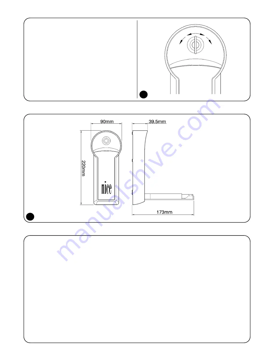
4
1. Turn the key 90° in the required direction;
Fig. 3
2. Open the release handle 90°;
Fig. 4
3. Unscrew the protection panel screw and remove it;
Fig. 5
4. Remove the protection panel counter spring;
Fig. 6
5. Place the switch against the wall and mark the screw hole posi-
tions;
6. Drill four holes and fix the switch to the wall using the 4 screws
and suitable dowels;
Fig. 7
7. Pass the steel wire as far as the release system leaving 20mm of
wire outside the sheath;
8. Remove the cover very carefully (A) and move the cursor to the
position shown in the illustration, and unscrew the grub screw;
Fig. 8
9. Insert the steel wire block it in position with the grub screw;
SCREW VERY TIGHTLY
;
Fig. 8b
10. Adjust the wire tension keeping in mind that the automatism will
result unblocked in the present position;
11. Replace the cover in position as in point 8;
12. Insert the spring in its housing and replace the protection guard
(B). Fixing it in position with the screws
Fig. 9
1) Description
KIO can be operated using a key switch with courtesy light or a
release switch. When the key is turned from vertical psition about
30°, two contacts are available: one in clockwise direction, and the
other in the opposite direction. When the key is turned further (in
either direction) the handle will open, and the release system will
function.
2) Dimensions
3) Fixing instructions
1
2
Release
Release
Op
Cl
Содержание KIO
Страница 2: ......
Страница 26: ...6 9 3 4 5 12 7 8b 13 8 11 14 A B C ...


