background image

Hot gas temperature

Stop with automatic restart:

The compressor stops when the temperature (BT14)
exceeds 135 °C.

Stop with manual restart:

The above has occurred 3 times within 240 minutes.

Restart when (BT14) is below 60 °C.

High pressure switch (BP10)

The compressor stops when the pressure exceeds
32 °C. The alarm can be reset manually when the
pressure falls below 25 bar.

Low pressure switch (BP2)

The compressor stops when the pressure has fallen
below 0.2 bar. The alarm can be reset manually when
the pressure exceeds 0.7 bar.

Working area

15

10

20

25

30

35

40

45

50

55

60

65

70

-20

-25

-30

-15

-10

-5

0

5

10

15

20

25

30

35

45

40

Water temperature

°C

°C

Outdoor air temperature

Supply temperature
Return temp

During shorter time it is allowed to have lower working
temperatures on the water side, e.g. during start up.

High supply temperature

Blocks the compressor when the supply temperature
(BT12) is higher than maximum supply temperature.

Resets when supply temperature (BT12) is lower than
max supply temperature and the return temperature
is lower than maximum return temperature minus dif-
ference in menu A3.

High return temperature

Blocks the compressor when the return temperature
(BT3) is higher than maximum return temperature.

Resets when the return temperature (BT3) is lower than
maximum return temperature minus diff in menu A3.

MP alarm (07)

MP alarm (07) is obtained if main contactor (QA51,
motor circuit breaker (FC2), high pressure switch (BP10)
or phase monitor *BA1) have tripped.

Main contactor (QA51)

If any of the following conditions are met, the main
contactor breaks (QA51).

High pressure switch (BP10) has tripped

The fan's (GO1) klixon has tripped.

Motor circuit breaker (FC2)

Tripped motor circuit breaker is reset manually .

Fuse

F2300

13 A

14 kW

16 A

20 kW

Phase monitor (BA1)

Trips if:

a phase falls below ~160 V.

incorrect phase sequence

Time conditions compressor

Minimum time between stop and start is 5 min.

Minimum time from start to next start is 20 min.

Quick start occurs in menu S2.

NIBE™ F2300

Chapter 4 |

Compressor protection

10

4 Compressor protection

Содержание F2300

Страница 1: ...Service manual LEK NIBE F2300 Air water heat pump SEM GB 1335 1 M11450 ...

Страница 2: ......

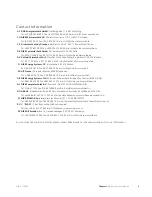
Страница 3: ...alarm 07 10 Main contactor QA51 10 Motor circuit breaker FC2 10 Phase monitor BA1 10 Time conditions compressor 10 5 Component description 11 Compressor GQ10 11 Other components 11 Electronics 11 Sensors 12 Reference designation 14 6 Troubleshooting 15 Alarm list 15 Troubleshooting guide 17 Function check relays components 22 7 Component replacement 23 Basic 23 Main components 24 Circuit board and...

Страница 4: ...rective 2006 42 EG Children must be instructed supervised to ensure that they do not play with the appliance This is an original handbook It must not be translated without approval from NIBE We reserve the right to make design modifications without prior notice NIBE 2011 Symbols NOTE This symbol indicates danger to machine or person Caution This symbol indicates important information about what yo...

Страница 5: ...uenau FR Tel 03 88 06 24 10 Fax 03 88 06 90 15 E mail info nibe fr www nibe fr NIBE Energy Systems Ltd 3C Broom Business Park Bridge Way Chesterfield S41 9QG GB Tel 0845 095 1200 Fax 0845 095 1201 E mail info nibe co uk www nibe co uk NIBE Energietechniek B V Postbus 2 NL 4797 ZG WILLEMSTAD NB NL Tel 0168 477722 Fax 0168 476998 E mail info nibenl nl www nibenl nl ABK AS Brobekkveien 80 0582 Oslo P...

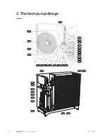
Страница 6: ...General LEK 4 41 6 50 7 3 7 4 3 7 3 41 3 41 41 41 0 LEK 7 3 8 3 7 7 3 7 3 NIBE F2300 Chapter 2 The heat pump design 4 2 The heat pump design ...

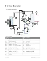
Страница 7: ...ure sensor evaporator BT16 Temperature sensor suction gas BT17 Temperature sensor ambient BT28 Electrical components Joint card sensor AA100 Joint card AA101 Compressor heater EB10 Drip tray heater EB11 Collar heater EB13 Fan GQ1 Cooling components Evaporator EP1 Condenser EP2 Compressor GQ10 Drying filter HS1 Expansion valve QN1 4 way valve QN2 Solenoid valve fluid injection QN30 Solenoid valve s...

Страница 8: ...eating cable 250 mA F3 Automatic protection 10 A 30 mA FB1 Motor fuse FC2 Contactor main contactor QA51 Contactor low speed fan QA52 Contactor high speed fan QA53 Terminal block incoming supply X1 Terminal block external supply X2 Terminal block charge pump external heater X3 Terminal block common alarm X4 Terminal block thermostat compressor blocking X5 Terminal block X6 Designations in component...

Страница 9: ...ar BP1 Compressor GQ10 Low pressure pressostat BP2 Drying filter HS1 High pressure switch 32 bar BP10 Fan motor M Temperature sensor return BT3 Expansion valve QN1 Temperature sensor condenser supply line BT12 4 way valve QN2 Temperature sensor hot gas BT14 Solenoid valve fluid injection QN30 Temperature sensor fluid pipe BT15 Solenoid valve subcooling QN31 Temperature sensor evaporator in BT16 Ex...

Страница 10: ... high temp Onreturnlineatthecondens er Return pipe BT3 Stopping the compressor at high temp On supply line at the con denser Flow pipe BT12 Stopping the compressor at high temp On hot gas pipe after the compressor Discharge BT14 View On the liquid line after the condenser Fluid pipe BT15 Starting and stopping defrosting On the lower part of the nozzle pipe Evaporator BT16 View On the suction pipe ...

Страница 11: ...ed QN10 switches to the heating system The heat pump works to a calculated set point value on the supply line If the heat pump cannot sup ply the whole heating demand additional heat EB1 and immersion heater EB20 are connected TIP Several system principles available at www nibe se docking Refer to the Installer manual for description of possible docking alternatives Installation requirements heati...

Страница 12: ...ure Resets when supply temperature BT12 is lower than max supply temperature and the return temperature is lower than maximum return temperature minus dif ference in menu A3 High return temperature Blocks the compressor when the return temperature BT3 is higher than maximum return temperature Resets when the return temperature BT3 is lower than maximum return temperature minus diff in menu A3 MP a...

Страница 13: ...V 43 W 1230 Ω Compressor heating EB 10 230 V 284 W 213 3 Ω Drip tray heater EB 11 230 V 275 W 192 4 Ω Collar heater EB 13 Voltage Fuse Output Ohm Component 230 V T100 mA 15 W 3527 Ω KVR 10 10 230 V T250 mA 45 W 1175 Ω KVR 10 30 230 V T500 mA 90 W 588 Ω KVR 10 60 Electronics Control card with display AA21 Jumpers on the edge connector J9 on the control card give the compressor size which affects ti...

Страница 14: ...1 587 4 348 45 1 426 3 583 50 1 278 2 968 55 1 136 2 467 60 1 007 2 068 65 0 891 1 739 70 0 785 1 469 75 0 691 1 246 80 0 607 1 061 85 0 533 0 908 90 0 469 0 779 95 0 414 0 672 100 Data for hot gas sensor BT14 Voltage V Resistance kOhm Temperature C 4 81 118 7 40 4 77 96 13 45 4 72 78 30 50 4 66 64 11 55 4 59 52 76 60 4 51 43 64 65 4 43 36 26 70 4 33 30 27 75 4 22 25 38 80 4 10 21 37 85 3 97 18 07...

Страница 15: ... 03 19 43 25 3 82 15 13 20 3 58 11 88 15 3 33 9 392 10 3 07 7 481 5 2 80 6 000 0 2 54 4 844 5 2 28 3 935 10 2 03 3 217 15 1 80 2 644 20 1 59 2 186 25 1 39 1 817 30 1 22 1 518 35 1 07 1 274 40 0 93 1 075 45 0 81 0 911 50 0 71 0 775 55 0 62 0 662 60 0 54 0 568 65 0 47 0 490 70 0 41 0 4233 75 0 36 0 367 80 0 32 0 320 85 0 28 0 280 90 0 25 0 245 95 0 22 0 216 100 13 Chapter 5 Component description NIB...

Страница 16: ...standard sensor Temperature sensor condenser supply line BT12 Tsupply EMMY hot sensor Temperature sensor hot gas BT14 Thot g EMMY standard sensor Temperature sensor fluid pipe BT15 Tliquid EMMY cold sensor Temperature sensor evaporator in BT16 Tevap EMMY cold sensor Temperature sensor suction gas BT17 Tsuc EMMY cold sensor Temperature sensor ambient BT28 Toutdoor Goes via fuse that breaks all thre...

Страница 17: ...tted range Faulty wiring between the units or connections If communication has been interrupted for five minutes a Communication alarm is given Communication alarm 09 Heatingmediumcirculatesthroughthecondens er in wrong direction The supply temperature sensor BT12 is lower than the return line sensor BT3 two minutes after compressor start Incorrectly in stalled sensor supply and re turn line senso...

Страница 18: ...rature BT3 is greater than maximum return line Does not apply during defrosting High re turn tem perature 04 Restarts when the pressure switch is reset Compressor blocked HP sensor BP1 interrupted be low or within 2 minutes after de frosting Defrost ing HP alarm 10 Resetswhentheambienttemper ature BT28 is less than 38 C Compressor blocked Stationary relay is activated Addi tional heat relay not ac...

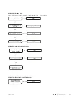
Страница 19: ...RUUHFW SUHVVXUH V WKH SUHVVXUH VZLWFK FRUUHFWO FRQQHFWHG FWLRQ 12 12 FWLRQ V WKH IDQ FRUUHFW FWLRQ 12 6 V WKH UHIULJHUDQW FLUFXLW LQWDFW FWLRQ 12 DFN RI KHDWLQJ PHGLXP RU RWKHU IDXOW LQ WKH FRROLQJ FLUFXLW RQWDFW DQ DXWKRULVHG UHIULJHUDWLRQ WHFKQLFLDQ 6 17 Chapter 6 Troubleshooting NIBE F2300 ...

Страница 20: ...witch correctly connected Action NO NO Action Check the heating medium pump Open any radiator thermostats Check the particle filter NO Fault in cooling circuit Contact an authorised refrigeration technician NO Reset the alarm Has the alarm been acknowledged YES High pressure switch BP10 or the fan s GQ10 internal Klixon has tripped remedy NO High pressure switch BP10 Klixon YES Does closing occur ...

Страница 21: ... 5HSODFH 12 12 FWLRQ 5HSODFH 12 V WKH MRLQW FDUG 2 6 5HSODFH 12 Alarm 09 communication alarm UH WKH LQWHUQDO FRQQHFWLRQV IRU FRPPXQLFDWLRQ FRUUHFW 6 6 V WKH FRPPXQLFDWLRQ FDEOH LQWDFW V WKH FRPPXQLFDWLRQ FDEOH FRUUHFWO FRQQHFWHG FWLRQ 12 12 FWLRQ Alarm 12 Incorrectly installed sensor RHV WKH KHDWLQJ PHGLXP FLUFXODWLRQ UXQ WKURXJK WKH FRQGHQVHU LQ WKH ULJKW GLUHFWLRQ FWLRQ 12 19 Chapter 6 Troublesh...

Страница 22: ...IURVWLQJ FDQFHOOHG E ORZ WHPSHUDWXUH RQ 7 EHORZ r RU 7 EHORZ r 6 KHFN IORZ WKURXJK WKH FRQGHQVHU GMXVW WKH YDOXH LQ PHQX 12 Alarm 16 short operating times 12 V WKH RSHUDWLQJ WKHUPRVWDW VHW WRR KLJK V WKH IORZ WKURXJK WKH FRQGHQVHU WRR ORZ FWLRQ 6 6 FWLRQ 12 V WKH YDOXH VHW WRR KLJK J VWRS FWLRQ 6 NIBE F2300 Chapter 6 Troubleshooting 20 ...

Страница 23: ...Alarm 17 hot gas alarm 6 V WKH UHIULJHUDQW ILOOLQJ FRUUHFW V WKH RYHUKHDWLQJ FRUUHFW FWLRQ 12 12 FWLRQ 6 V WKH FRPSUHVVRU LQWDFW 12 FWLRQ 21 Chapter 6 Troubleshooting NIBE F2300 ...

Страница 24: ...id valve subcooling QN31 K6 Compressor heater EB10 K7 Heater condensation EB11 K8 Collar heater EB13 K9 Compressor GQ10 K10 Charge pump Sometimes referred to as circ Pump GP12 K11 Alarm relay Output K12 External heating EB14 Stationary indication Stationary relay on control card Additional heat Additional heat relay on control card NIBE F2300 Chapter 6 Troubleshooting 22 ...

Страница 25: ...n NOTE The door is opened using a Torx 25 screw driver Removing electrical cabinet Unscrew the screws and lift off the cover LEK Dismantling motor module Unscrew the screws and lift off the cover LEK 23 Chapter 7 Component replacement NIBE F2300 7 Component replacement ...

Страница 26: ...ews 2 Remove the front panel s four screws and then the two screws for the side pan el RQQHFWLRQ SURWHFWLRQ RQQHFWLRQ FDEOH 3 Remove the compressor insulation and the terminal protectionattheconnection 4 Disconnect the connection cables NIBE F2300 Chapter 7 Component replacement 24 ...

Страница 27: ...g circuit and ensure that no refriger ant remains before you con tinue OLS 7 Disconnect the pipes for suction gas and hot gas 8 Pull off the clips on the bolts to the compressor 9 Lift the compressor out 10 Reassemble in reverse or der 25 Chapter 7 Component replacement NIBE F2300 ...

Страница 28: ...screws 2 Remove the front panel s four screws and then the two screws for the side pan el 3 Cut off the cable tie for the wiring and pipe to the evap orator 4 Then pull the panel out until the expansion valve is accessible NIBE F2300 Chapter 7 Component replacement 26 ...

Страница 29: ...nt remains before you con tinue 6 Remove the pipe insulation coveringthebulbandexpan sion valve 7 Slacken off the bulb for the expansion valve 8 Remove the pipe and re move the valve 9 Reassemble in reverse or der 27 Chapter 7 Component replacement NIBE F2300 ...

Страница 30: ...ur screws 2 Remove the front panel s four screws and then the three screws for the side panel 3 Disconnect the fan cable s electrical connector 6FUHZ 4 Remove the fan grille by slackening off the four screws NIBE F2300 Chapter 7 Component replacement 28 ...

Страница 31: ...n the fan motor 6 Reassemble in reverse or der Condensation water trough WM5 DQGOH 7URXJK RQGHQVDWLRQ ZDWHU SLSH 1 Remove the condensation pipe 2 Fold the two black handles down 3 Remove the trough 29 Chapter 7 Component replacement NIBE F2300 ...

Страница 32: ...incoming supply 2 Remove the cover and open the electrical cabinet on the heat pump 6XSSRUW 6XSSRUW 6XSSRUW 6XSSRUW 3 Remove the edge board connectorsandthenthefour supports 4 Remove the control card 5 Transfer the edge board connectors to the new card NIBE F2300 Chapter 7 Component replacement 30 ...

Страница 33: ...Electrical circuit diagram 31 Chapter 8 Technical data NIBE F2300 8 Technical data ...

Страница 34: ...NIBE F2300 Chapter 8 Technical data 32 ...

Страница 35: ...33 Chapter 8 Technical data NIBE F2300 ...

Страница 36: ...NIBE F2300 Chapter 8 Technical data 34 ...

Страница 37: ...5 Ø 40 400 mm Fritt utrymme bakom Fritt utrymme framför Min avstånd vid användning av flera F2300 600 mm 3000 mm 400 mm Minimalt fritt utrymme 600mm Minimalt fritt utrymme 0LQLPXP IUHH VSDFH UHH VSDFH EHKLQG UHH VSDFH LQ IURQW 0LQLPXP IUHH VSDFH 0LQLPXP GLVWDQFH GXULQJ XVH RI VHYHUDO 35 Chapter 8 Technical data NIBE F2300 ...

Страница 38: ... 2 97 9 41 3 03 3 10 kW kW 7 35 Delivered Supplied power COPEN14511 13 28 5 15 2 58 9 72 3 66 2 65 kW kW 7 45 Delivered Supplied power COPEN14511 10 37 4 2 2 47 7 49 2 96 2 53 kW kW 15 35 Delivered Supplied power COPEN14511 10 73 4 97 2 16 7 74 3 52 2 20 kW kW 15 45 Delivered Supplied power COPEN14511 Electrical data 400V 3NAC 50 Hz Rated voltage 16 12 Arms Max operating current heat pump 12 8 8 2...

Страница 39: ...utput is reduced by about 10 2 Rated outputs including defrosting according to EN14511 at heating medium flow corresponding to DT 5 K at 7 45 3 Max permitted impedance in the mains connected point in accordance with EN 61000 3 11 Start currents can cause short voltage dips that could affect other equipment in unfavourable conditions If the impedance in the mains connection point is higher than tha...

Страница 40: ...0 15 10 5 0 5 10 15 20 25 30 35 45 40 Water temperature C C Outdoor air temperature Supply temperature Return temp During shorter time it is allowed to have lower working temperatures on the water side e g during start up NIBE F2300 Chapter 8 Technical data 38 ...

Страница 41: ...h BP10 10 High return temperature 10 High supply temperature 10 Hot gas temperature 10 I Important information 2 Document information 2 Safety information 2 Internal outputs 22 L Low pressure switch BP2 10 M Main components 24 Main contactor QA51 10 Marking 2 Motor circuit breaker FC2 10 MP alarm 07 10 O Other components 11 P Phase monitor BA1 10 Principle of operation 7 R Reference designation 14...

Страница 42: ......

Страница 43: ...NIBE AB Sweden Hannabadsvägen 5 Box 14 SE 285 21 Markaryd info nibe se www nibe eu ...

Отзывы: