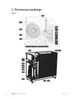
Pipe connections
Connection, heating medium out of F2300, G1
1/4" (Ø35 mm)
XL1
Connection, heating medium in to F2300, G1
1/4" (Ø35 mm)
XL2
Service connection, high pressure
XL20
Service connection, low pressure
XL21
Connection, drip tray drain (Ø40 mm)
XL40
Sensors etc.
High pressure switch (29 bar)
BP1
Low pressure pressostat
BP2
High pressure switch (32 bar)
BP10
Temperature sensor, return
BT3
Temperature sensor, condenser supply line
BT12
Temperature sensor, hot gas
BT14
Temperature sensor, fluid pipe
BT15
Temperature sensor, evaporator
BT16
Temperature sensor, suction gas
BT17
Temperature sensor, ambient
BT28
Electrical components
Joint card, sensor
AA100
Joint card
AA101
Compressor heater
EB10
Drip tray heater
EB11
Collar heater
EB13
Fan
GQ1
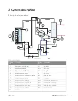
Cooling components
Evaporator
EP1
Condenser
EP2
Compressor
GQ10
Drying filter
HS1
Expansion valve
QN1
4-way valve
QN2
Solenoid valve, fluid injection
QN30
Solenoid valve, subcooling
QN31
Expansion valve, subcooling
QN34
Non-return valve
RM1
Miscellaneous
Type plate
PF1
Serial number
PF3
Cable gland, incoming supply
UB1
Condensation water trough
WM5
Designations in component locations according to
standard IEC 81346-1 and 81346-2.
5
Chapter 2 |
The heat pump design
NIBE™ F2300
Содержание F2300
Страница 1: ...Service manual LEK NIBE F2300 Air water heat pump SEM GB 1335 1 M11450 ...
Страница 2: ......
Страница 33: ...Electrical circuit diagram 31 Chapter 8 Technical data NIBE F2300 8 Technical data ...
Страница 34: ...NIBE F2300 Chapter 8 Technical data 32 ...
Страница 35: ...33 Chapter 8 Technical data NIBE F2300 ...
Страница 36: ...NIBE F2300 Chapter 8 Technical data 34 ...
Страница 42: ......
Страница 43: ...NIBE AB Sweden Hannabadsvägen 5 Box 14 SE 285 21 Markaryd info nibe se www nibe eu ...


