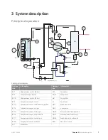
Sensor internal
Sensors etc.
Function
Location
Name
Designa-
tion
Protects the compressor against pressures that are
too high during defrosting.
On hot gas line.
High pressure switch
(29 bar)
BP1
Protects the compressor against pressures that are
too low.
On suction gas line.
Low pressure
pressostat
BP2
Protects the compressor against pressures that are
too high during normal operation.
On hot gas line.
High pressure switch
(32 bar)
BP10
Stopping the compressor at high temp.
On return line at the condens-
er.
Return pipe
BT3
Stopping the compressor at high temp.
On supply line at the con-
denser.
Flow pipe
BT12
Stopping the compressor at high temp.
On hot gas pipe after the
compressor.
Discharge
BT14
View.
On the liquid line after the
condenser.
Fluid pipe
BT15
Starting and stopping defrosting.
On the lower part of the
nozzle pipe
Evaporator
BT16
View.
On the suction pipe before
the compressor.
Suction gas
BT17
Stops comp at high and low outdoor temperature.
Switches fan speed.
Permits/blocks defrosting.
On the side panel next to the
upper part of the evaporator
bend.
Surrounding area
BT28
NIBE™ F2300
Chapter 3 |
System description
8
Содержание F2300
Страница 1: ...Service manual LEK NIBE F2300 Air water heat pump SEM GB 1335 1 M11450 ...
Страница 2: ......
Страница 33: ...Electrical circuit diagram 31 Chapter 8 Technical data NIBE F2300 8 Technical data ...
Страница 34: ...NIBE F2300 Chapter 8 Technical data 32 ...
Страница 35: ...33 Chapter 8 Technical data NIBE F2300 ...
Страница 36: ...NIBE F2300 Chapter 8 Technical data 34 ...
Страница 42: ......
Страница 43: ...NIBE AB Sweden Hannabadsvägen 5 Box 14 SE 285 21 Markaryd info nibe se www nibe eu ...


