


Control conditions, cold outdoor air
႑
When the outdoor air temperature (channel T1) drops
below the set temperature in channel A7 the heat pump
stops and indicates 03 in channel S1. Both the additional
relay and the downtime relay are then activated at the
same time.
႑
If the outdoor air sensor registers a temperature that is
at least 2.1 ° C higher than the set temperature in channel
A7, a time counter starts.
႑
When the time counter has reached 45 minutes, both
the additional relay and downtime relay deactivate to
obtain a more comfortable temperature for the com-
pressor to start at.
႑
When a further 15 minutes have passed, the compressor
is permitted to start and the additional relay activates a
few seconds later. However, the downtime relay is deac-
tivated.
႑
If the outdoor temperature drops below channel A7 +
2.1 °C at any time during these 60 minutes, the counter
is reset and does not start to count again until the tem-
perature is sufficiently high again.
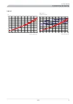
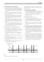
B = Set temperature for cold outdoor air (channel A7).
A = Set temperature for cold outdoor air + 2.1 °C.
1.
The outdoor air temperature (channel T1) drops below
the set temperature in channel A7 (B). The heat pump
stops and both the relays are activated.
2.
The outdoor air temperature is 2.1 °C above the set
temperature in channel A7 (A). A time counter starts
from 0.
3.
The outdoor temperature falls below A. The timer is reset
and stopped.
4.
The outdoor air temperature returns to above A. The
time counter starts again (from 0).
5.
The time counter has counted to 45 minutes. Both relays
are deactivated.
6.
The time counter has counted to 60 minutes. The com-
pressor is permitted to start again.
utelufttemp.
A
B
1
2
3
4
5
6
Utelufttemperatur
2XWGRRU WHPSHUDWXUH
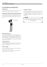
Tip:
It is heat pump’s outdoor sensor that applies.
If VVM 300/SMO 10 is connected it is not the value in menu
4.0 but the value in the outdoor air temperature in menu
5.9 which is used.
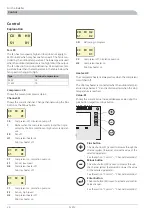
Control conditions defrosting
႑
A time counter counts up every minute if the compressor
is running and the temperature of the evaporator sensor
(channel T7) falls below the setting in channel A9
႑
If the time counter has reached the setting in channel
A8, defrosting starts.
Defrosting occurs as follows:
1.
The four way valve shifts to defrosting
2.
The fan stops and the compressor continues to run.
3.
When defrosting is complete the four way valve shifts
back to heating mode and after 30 seconds the fan
starts.
4.
Outdoor sensors is locked and the high return temperat-
ure alarm is blocked during and for two minutes after
defrosting.
There are 4 possible reasons for defrosting to finish:
1.
The temperature of the evaporator sensor has reached
the set temperature in channel A10. Normal stop.
2.
Defrosting has run longer than the setting in channel
A11. Can be due to insufficient energy in the heat
source, that the sensor on the evaporator is poorly posi-
tioned and gives too low a temperature (in the event of
cold outdoor air).
3.
The temperature on the return sensor falls below 10°C.
4.
The high-pressure pressostat deploys during defrosting.
Indicated as alarm 10 in channel S1. The compressor
stops when this occurs and if the pressure has dropped
2 minutes later it can be started as normal, otherwise
the permanent high-pressure alarm occurs (alarm 06).
႑
The temperature on the flow sensor falls below 4°C.
23
F2015
For the Installer
Control
Содержание F2015
Страница 1: ...INSTALLATION AND MAINTENANCE INSTRUCTIONS MOS GB 1008 3 F2015 031239 F2015 LEK ...
Страница 2: ......
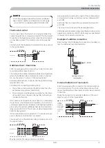
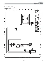
Страница 27: ...Electrical circuit diagram 1x230V 6 11 kW 25 F2015 Miscellaneous Electrical circuit diagram ...
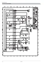
Страница 28: ...F2015 26 Miscellaneous Electrical circuit diagram ...
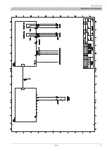
Страница 29: ...27 F2015 Miscellaneous Electrical circuit diagram ...
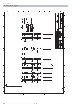
Страница 30: ...F2015 28 Miscellaneous Electrical circuit diagram ...
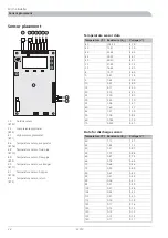
Страница 31: ...Technical specifications Component positions LEK LEK 29 F2015 Miscellaneous Technical specifications ...
Страница 40: ...F2015 38 ...
Страница 41: ...39 F2015 ...
Страница 42: ...F2015 40 ...
Страница 43: ......


