


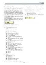


Control
Explanation
C0
F0
H0
S1
01
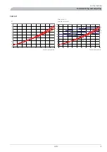
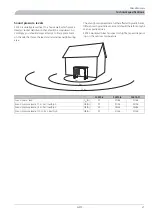
Fan: F0
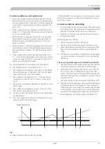
The fan has two speeds, high and low (does not apply to
F2015-6 kW which only has one fan speed). The fan is con-
trolled by the outdoor temperature. The lower speed is used
when the outdoor temperature is too high to limit the output.
The fan does not run during defrosting. At an outdoor tem-
perature lower than the temperature in the table below the
fan speed is changed to high.
Outdoor temperature
Type
15
8 kW
15
11 kW
Compressor: C0
Shows the present compressor status.
Channel: S1
Shows the current channel. Change channels using the Plus
button or the Minus button.
C0
F0
H1
S1
01
Compressor off, circulation pump off
C0
Flashes when the compressor wants to start but is pre-
vented by the time conditions or high return temperat-
ure.
C
Fan off
F0
Compressor heater on
H1
Drip tray heater off
C1
F1
H0
S1
01
Compressor on, circulation pump on
C1
Fan on, low speed
F1
Compressor heater off
H0
Drip tray heater off
C1
F2
H2
S1
01
Compressor on, circulation pump on
C1
Fan on, high speed
F2
Compressor heater off
H2
Drip tray heater on
CD
F0
H2
S1
02
Defrosting in progress
CD
CC
F0
H3
S1
01
Compressor off, circulation pump on
CC
Compressor heater on
H3
Drip tray heater on
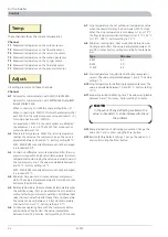
Heater: H0
The compressor heater is always active when the compressor
is switched off.
The drip tray heater is connected when the outdoor temper-
ature drops below 2 °C and is disconnected when the stop
temperature is reached.
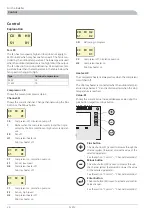
Value: 01
Shows the current value. Increase/decrease value using the
plus button respective minus button.
34
Plus button
The plus button (37) is used to browse through the
channel system (forwards) or raise the value of the
selected parameter.
See the section “Control” – “Channel description”
Minus button
The minus button (38) is used to browse through
the channel system (backwards) or lower the value
of the selected parameter.
See the section “Control” – “Channel description”
Enter button
The Enter button (39) is used to activate and confirm
value changes.
See the section “Control” – “Channel description”
F2015
20
For the Installer
Control
Содержание F2015
Страница 1: ...INSTALLATION AND MAINTENANCE INSTRUCTIONS MOS GB 1008 3 F2015 031239 F2015 LEK ...
Страница 2: ......
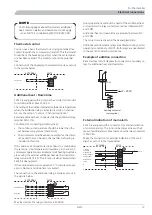
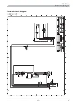
Страница 27: ...Electrical circuit diagram 1x230V 6 11 kW 25 F2015 Miscellaneous Electrical circuit diagram ...
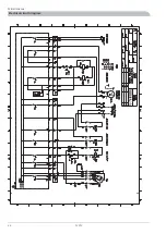
Страница 28: ...F2015 26 Miscellaneous Electrical circuit diagram ...
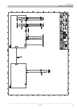
Страница 29: ...27 F2015 Miscellaneous Electrical circuit diagram ...
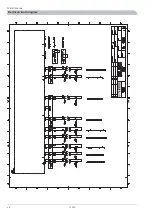
Страница 30: ...F2015 28 Miscellaneous Electrical circuit diagram ...
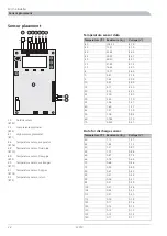
Страница 31: ...Technical specifications Component positions LEK LEK 29 F2015 Miscellaneous Technical specifications ...
Страница 40: ...F2015 38 ...
Страница 41: ...39 F2015 ...
Страница 42: ...F2015 40 ...
Страница 43: ......


