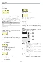
Temp.
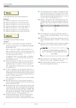
These channels show the current temperatures.
Channel
Measured temperature on the outdoor sensor.
T1
Measured temperature on the flow line sensor.
T2
Measured temperature on the return line sensor.
T3
Measured temperature on the suction gas sensor.
T4
Measured temperature on the hot gas sensor.
T5
Measured temperature on the fluid pipe sensor.
T6
Measured temperature on the evaporator sensor.
T7
Adjust.
All setting are made on these channels.
Channel
Address for communication with SMO 10/VVM 300.
A1
Address for communication with METROAIR Styring/MET-
ROAIR 300/EVP 500.
When connecting to VVM this channel should be on 1.
When connecting to SMO 10 this must be selected so that
each F2015 in the system receives a unique address (1 – 9)
for communication with SMO 10.
For example 3 x F2015 in the same system are allocated
the addresses 1, 2 and 3. The F2015 that produces hot
water should be set to 1.
Max return temperature. When the return temperature
reaches the set value the compressor stops. The value is
adjustable between 25 and 50 °C. Factory setting 48 °C.
A2
With SMO/VVM connected this menu cannot be changed,
it is locked at 50 °C.
Connection difference return temperature. After the com-
pressor is stopped for a high return temperature, the return
temperature should drop by the set value in order to permit
the compressor to start. The value is adjustable between 0
and 10 °C. Factory setting is 4 °C.
A3
With SMO/VVM connected this menu cannot be changed,
it is locked at 2 °C.
Minimum time period in minutes between compressor
starts. The value is adjustable between 20 and 60 minutes.
Factory setting 20 minutes.
A4
Balance temperature, the set outdoor air temperature when
the additional relay (14) can be activated from channel A6
without affecting compressor operations. Additional heat
relay (14) is activated first after the set time on channel A6.
The value can be set between -15 (set stop temperature,
channel A7) and +10 °C. Factory setting is 0 °C.
A5
Continuous operating time with the compressor before
additional heat is permitted. The value is adjustable
between 0 and 120 minutes. Factory setting 120 minutes.
A6
Stop temperature, the set outdoor air temperature value
when the downtime relay (16) is activated, F2015 stops.
When the stop temperature is set between -7 and -15 °C
the flow temperature is limited linearly from -7 °C / 55 °C
to -15 °C / 45 °C. Factory setting is -15 °C.
A7
Minimum running time, heat production before new de-
frosting is permitted. The value is adjustable between 10
and 90 minutes. Factory setting according to the table be-
low.
A8
Minutes
Type
60
6 kW
50
8 kW
45
11 kW
Start temperature for permitted defrosting (evaporator
sensor). The value is adjustable between 1 and 5 °C. Factory
setting 1 °C.
A9
Stop temperature for defrosting (evaporator sensor). The
value is adjustable between 10 and 40 °C. Factory setting
10 °C.
A10
Longest permitted defrosting time. The value is adjustable
between 5 and 12 minutes. Factory setting 7 minutes.
A11
NOTE
In the event of any defrosting problems, the
value in channel A11 can be increased to relieve
the problem.
Manual activation of defrosting procedure. Change the
value 0 to 1 and confirm using the Enter button.
A12
Restore factory default settings. Change the value 0 to 1
and confirm using the Enter button.
A13
F2015
22
For the Installer
Control
Содержание F2015
Страница 1: ...INSTALLATION AND MAINTENANCE INSTRUCTIONS MOS GB 1008 3 F2015 031239 F2015 LEK ...
Страница 2: ......
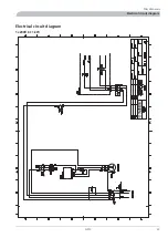
Страница 27: ...Electrical circuit diagram 1x230V 6 11 kW 25 F2015 Miscellaneous Electrical circuit diagram ...
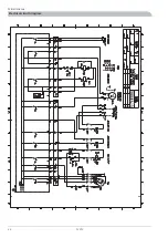
Страница 28: ...F2015 26 Miscellaneous Electrical circuit diagram ...
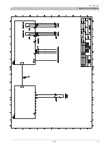
Страница 29: ...27 F2015 Miscellaneous Electrical circuit diagram ...
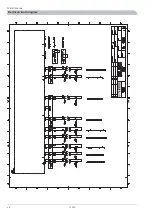
Страница 30: ...F2015 28 Miscellaneous Electrical circuit diagram ...
Страница 31: ...Technical specifications Component positions LEK LEK 29 F2015 Miscellaneous Technical specifications ...
Страница 40: ...F2015 38 ...
Страница 41: ...39 F2015 ...
Страница 42: ...F2015 40 ...
Страница 43: ......


