Appendix B
5B Series Module Data Sheets
©
National Instruments Corporation
B-41
SC-2311 User Manual
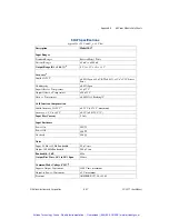
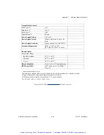
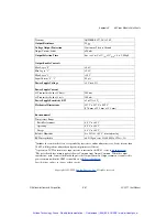
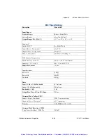
Transient
ANSI/IEEE C37.90.1-1989
Output Resistance
25
Voltage Output Protection
Continuous Short to Ground
Output Current Limit
±20 mA
Output Selection Time
6 µs to ±1 mV of V
out
@ C
load
= 0 to 2,000 pF
Output Enable Control
3
Max Logic "0"
+0.8 V
Min Logic "1"
+2.4 V
Max Logic "1"
+36 V
Input Current "0", "1"
0.5 µA
Power Supply Voltage
+5 V dc ±5%
Power Supply Current
@ Transmitter Load of 20 mA
200 mA
@ Transmitter Load of 4 mA
100 mA
Power Supply Sensitivity, RTI
±1 µV/% of V
s
Mechanical Dimensions
2.275" x 2.375" x 0.595"
(57.8 mm x 59.1 mm x 15.1 mm)
Environmental
Temperature Range
Rated Performance
-40˚C to +85˚C
Operating
-40˚C to +85˚C
Storage
-40˚C to +85˚C
Relative Humidity
0 to 95% @ +60˚C, noncondensing
RFI Susceptibility
±0.5% Span error @ 400 MHz, 5 Watt, 3 ft
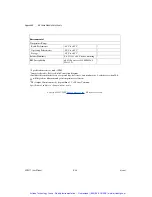
1
Includes the combined effects of repeatability, hysteresis, and nonlinearity error. Loads heavier than
50 k
will degrade nonlinearity and gain temperature coefficient.
2
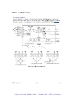
A precision 25
current-sense input resistor is internal to the 5B42 - refer to
block diagram
.
3
The user's board layout must separate Power Common from Output Common. When the output
switch is not used, connect the Enable Input to the Output Common. Output common is connected to
power common when the 5B42 is installed on a
5B Series backplane
.
Specifications subject to change without notice.
Copyright 1995-2000
Analog Devices, Inc.
All rights reserved.
Artisan Technology Group - Quality Instrumentation ... Guaranteed | (888) 88-SOURCE | www.artisantg.com

