e
Electro Industries/GaugeTech
Doc # E134-7-15 V1.01
12-2
12.3: Communication
12.3: Communication
n
Maximum registers per request, read or write, is 4 registers.
n
The device will operate with the following default parameters:
Address
247 (F7H)
Baud Rate
57600 Baud
Transmit Delay Time
20 csec
n
Certain situations will cause the device to operate with the above default parameters. See Chapter 5
for details of Default Mode.
12.4: Normal Mode
12.4: Normal Mode
n
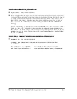
Energy readings are given to the device frequently. The device generates a pulse at each channel
after a certain energy increase.
n
Normal Operation consists of three processes:
1. The first process accepts writes to registers 04097 - 04112. Writes can be up to four registers
long and should end on the fourth register of a group (register 04100, or registers 04103-
04112 or registers 04109-04112). These writes can be interpreted as two-byte, four-byte,
six-byte or eight-byte energy readings. The reception of the first value for a given channel
provides the initial value for that channel. Subsequent writes will increment the Residual for
that channel by the difference of the old value and the new value. The previous value is then
replaced with the new value.
Attempting to write a value greater than the programmed Rollover Value for a given channel
is completely ignored and no registers are modified. If the difference is greater than half of
the programmed Rollover Value for a given channel, the write does not increment the
Residual but does update the Last Value. Overflow of the Residual is not prevented.
2. The second process occurs in the main loop and attempts to decrement the Residual by the
Programmed Energy/Pulse Value. If the Residual is greater than the Programmed
Energy/Pulse Value and the Pending Pulses Value for that channel is not maxed, then
Residual is decremented appropriately and the Pending Pulses is incremented by two,
signifying two more transitions and one more pulse.
3. The third process runs from a timer which counts off pulse widths from the Programmable
Minimum Pulse Width Values. If there are Pulses Pending for a channel and the delay has
passed, then the Pulses Pending is decremented for that channel and the Output Relay is
toggled.
Содержание I/O Module
Страница 2: ......
Страница 6: ...e Electro Industries Gauge Tech Doc E134 7 15 V1 01 iv ...
Страница 10: ...e Electro Industries Gauge Tech Doc E134 7 15 V1 01 viii ...
Страница 30: ...e Electro Industries GaugeTech Doc E134 7 15 V1 01 2 16 ...
Страница 44: ...e Electro Industries GaugeTech Doc E134 7 15 V1 01 4 8 ...
Страница 50: ...e Electro Industries GaugeTech Doc E134 7 15 V1 01 6 4 ...
Страница 52: ...e Electro Industries Gauge Tech Doc E 134 7 15 V1 01 7 2 ...
Страница 63: ...e Electro Industries GaugeTech Doc E134 7 15 V1 01 8 4 ...
Страница 65: ...e Electro Industries Gauge Tech Doc E 134 7 15 V1 01 9 2 ...
Страница 72: ...e Electro Industries GaugeTech Doc E134 7 15 V1 01 10 4 ...
Страница 74: ...e Electro Industries Gauge Tech Doc E 134 7 15 V1 01 11 2 ...
Страница 81: ...e Electro Industries Gauge Tech Doc E 134 7 15 V1 01 13 2 ...
Страница 87: ...e Electro Industries GaugeTech Doc E134 7 15 V1 01 14 4 ...
Страница 89: ...e Electro Industries Gauge Tech Doc E 134 7 15 V1 01 15 2 ...


