e
Electro Industries/Gauge Tech
Doc #
E 134-7-15 V1.01
15-1
Chapter 15
Chapter 15
Digital Status Input Modbus Register Map
Digital Status Input Modbus Register Map
n
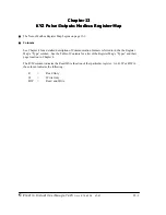
The Modbus Register Map for the Digital Status Input I/O Module (8DI1) begins on the page 15-3.
n
Columns
See Chapter 4 for a detailed description of Communication Formats referred to in the the Register
Map’s “Type” column. See the Table of Contents for a list of the Register Map’s “Types” and their
page location in Chapter 4.
The R/W column indicates the Read/Write function of that particular register. An R, W or R/W in
the column indicates the following:
R
=
Read Only
W
=
Write Only
R/W
=
Read and Write
Содержание I/O Module
Страница 2: ......
Страница 6: ...e Electro Industries Gauge Tech Doc E134 7 15 V1 01 iv ...
Страница 10: ...e Electro Industries Gauge Tech Doc E134 7 15 V1 01 viii ...
Страница 30: ...e Electro Industries GaugeTech Doc E134 7 15 V1 01 2 16 ...
Страница 44: ...e Electro Industries GaugeTech Doc E134 7 15 V1 01 4 8 ...
Страница 50: ...e Electro Industries GaugeTech Doc E134 7 15 V1 01 6 4 ...
Страница 52: ...e Electro Industries Gauge Tech Doc E 134 7 15 V1 01 7 2 ...
Страница 63: ...e Electro Industries GaugeTech Doc E134 7 15 V1 01 8 4 ...
Страница 65: ...e Electro Industries Gauge Tech Doc E 134 7 15 V1 01 9 2 ...
Страница 72: ...e Electro Industries GaugeTech Doc E134 7 15 V1 01 10 4 ...
Страница 74: ...e Electro Industries Gauge Tech Doc E 134 7 15 V1 01 11 2 ...
Страница 81: ...e Electro Industries Gauge Tech Doc E 134 7 15 V1 01 13 2 ...
Страница 87: ...e Electro Industries GaugeTech Doc E134 7 15 V1 01 14 4 ...
Страница 89: ...e Electro Industries Gauge Tech Doc E 134 7 15 V1 01 15 2 ...


