TRACE
MATE II-CTR
Chapter 5 TESTING
5.2
Table 5.2 Resistance versus Temperature in °C
(DIN 43760 RTD)
°C
R (ohms)
°C
R (ohms)
°C
R (ohms)
-40
84.27
80
130.89
200
175.84
-30
88.22
90
134.70
210
179.51
-20
92.16
100
138.50
220
183.17
-10
96.09
110
142.29
230
186.82
0
100.00
120
146.06
240
190.46
10
103.90
130
149.82
250
194.08
20
107.79
140
153.58
260
197.69
30
111.67
150
157.32
270
201.30
40
115.64
160
161.04
280
204.88
50
119.39
170
164.76
290
208.46
60
123.24
180
168.47
300
212.03
70
127.07
190
172.16
Ground Fault Testing
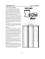
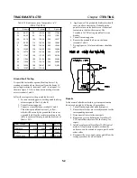
It is possible to simulate a ground fault on heater 1 by
creating a situation where the current from the heater 1’s
power input terminals, terminal 1 and 2, is not equal. As
shown in figure 5.2, this is done by connecting a resistor
across terminals 1 and 4.
Follow these steps to test the ground fault circuit:
1. Turn on incoming power. Set the gound fault trip
alarm setpoint to 30mA ( default ).
2. Turn off incoming power.
3. Connect a resistor between terminals 1 and 4.
This allows ground fault current I
G
to flow,
which will be seen by the ground fault sensor as
a ground fault. Size the resistor according to the
table to ensure sufficient ground fault current of
30mA ± 25%.
Heater Voltage
110
240
277 AC Volts
Resistance
2700
6200
6800
Ohms
Wattage
5
10
15
Watts
Voltage Rating
250
500
500 DC Volts
4. Apply power. The ground fault indicator should
come on after a short delay. It should not be
possible to turn on the heater even if the actual
temperature is below the setpoint. The
TraceMate II-CTR acts a ground fault circuit
breaker.
5. Turn off incoming power.
6. Remove the ground fault resistor between
terminals 1 and 4.
7. Re-apply power. All alarm indicators should be
off.
Repairs
In the event of a hardware failure, system operation can
be restored quickly by following this procedure:
1. Turn off incoming heater and alarm power.
2. Ensure that all wires are correctly marked for the
corresponding terminals.
3. Disconnect all wires to the terminals.
4. Remove any screws holding the TraceMate II-
CTR controller and return it to the factory for
repair.
5. Install a replacement TraceMate II-CTR control
module. A replacement module, without the
enclosure, can be ordered as a spare part. See the
order codes.
6. Reconnect the wires, apply power and follow the
testing procedure for a new control.


