background image

TRACE

MATE II-CTR

Chapter 3 APPLICATIONS

3.1

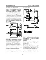
Mechanical Thermostat Replacement

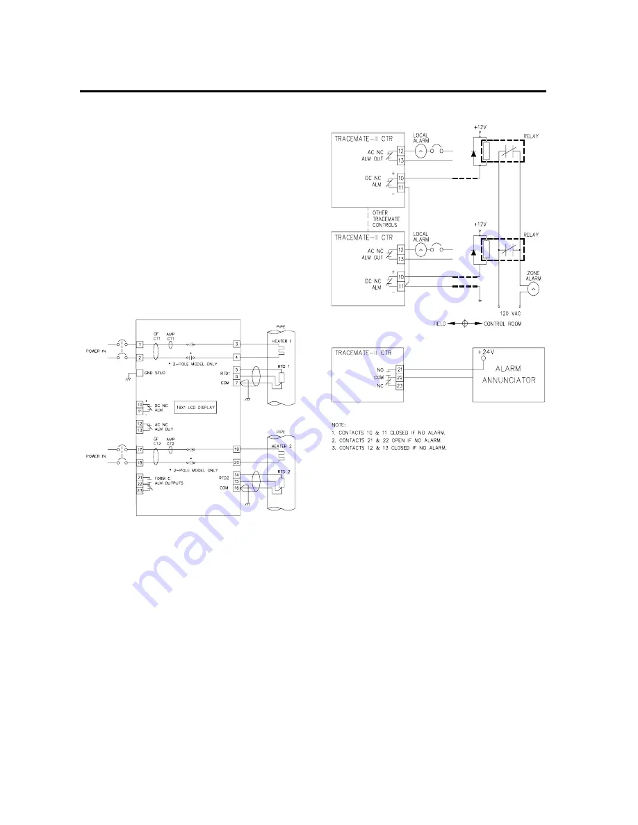
Mount the control unit near the pipe being traced in a
location with easy access. Replace the thermostat capil-
lary tube with an RTD mounted on the pipe and connect
the existing heater and power wires to the TraceMate II-
CTR 
as shown in Figure 3.1. A 16x1 LCD display is
mounted on the door of TraceMate II-CTR. Instant system
measurements such as pipe temperatures, heater currents,
ground fault currents, and heater on/off status can be seen
on the display. Also, the alarm status of each heater and
their causes are shown on the display. If control power is
not available, the LCD display will go off.
Advantage of this scheme over mechanical thermostats is:
easy setpoint adjustment, ground fault current protection,
early warning of system faults with TraceCheck system
exercising every 24 hours and rapid fault diagnosis in the
event of a problem.

Remote Zone Alarm

If a remote alarm is required, a number of TraceMate II-
CTR 
control alarms can be connected to give a remote
zone alarm indication in a control room as shown in
Figure 3.2. Once the alarm goes on, maintenance
personnel can be dispatched to the area. The heat trace
point with a problem can be identified by the alarm
messages on the LCD display. For a fast diagnosis and
repair, the alarm message on the display and the status
LED indicators in the TraceMate II-CTR identify the
exact nature of the problem. This simple connection
minimizes control room panel space, allowing a few LCD
displays and indicators to cover a complete plant.

Alarm Annunciator

If an alarm annunciator or programmable controller is
available, terminal 21, 22 & 23 can be used as a low cost

digital interface. These terminals are form C dry con-
tacts. A separate voltage source must be connected across
these terminals as shown in Figure 3.2 for the annuncia-
tor to sense the alarm logic.

Local Alarm

A local visual alarm indicator can also be connected to
the isolated AC alarm output terminals 12 and 13 as
shown in Figure 3.2.

Switching Requirements

Four different TraceMate II-CTR models are available to
accommodate different power rating of electric heat
trace. TM-2SIH1-RTD is rated single-pole 120VAC@
30A; TM-2SIH1-RTD-240V is rated single-pole
240VAC@30A; TM-2DIH2-RTD-208~240V is rated
dual-pole 208~240VAC@30A; TM-2SIH1-RTD-277V is
rated single-pole [email protected] to Figure2.2
Typical Wiring Diagram for power and heater wiring.

Figure 3.1 Thermostat Replacement

Figure 3.2 Alarm Wiring

Содержание TRACEMATE II-CTR

Страница 1: ...TRACEMATE II CTR OPERATOR S MANUAL ELECTRONIC THERMOSTAT ...

Страница 2: ... 3 Ground Connection 2 3 RTD Sensor Wiring 2 3 Alarm Wiring 2 4 3 Applications 3 1 Mechanical Thermostat Replacement 3 1 Remote Zone Alarm 3 1 Alarm Annunciator 3 1 Local Alarm 3 1 Switching Requirements 3 1 4 Operation 4 1 Alarms 4 1 Alarm Contacts 4 1 Alarm Messages 4 1 Alarm Indicators 4 1 Status Indicators 4 1 Alarm Reset 4 2 Heater Setpoint and Alarm Setpoints 4 2 5 Testing 5 1 Troubleshootin...

Страница 3: ...ve alarm package which includes LCD displaymessages and LED indicators for quick fault identification and a ground fault trip to minimize fire hazards Bycombining the control system monitoring and testing requirements of a heat trace control system into a general purpose control the TraceMate II CTR makes it possible to significantly upgrade systems at low installed cost In addition it is very fle...

Страница 4: ...ting Range TM 2SIH1 RTD 40 C to 50 C TM 2SIH1 RTD 240V 40 C to 50 C TM 2DIH2 RTD 208 240V 40 C to 50 C TM 2SIH1 RTD 277V 40 C to 50 C LCD display 20 C to 50 C Heater current derated Conformal Coating Boards conformal coated for hostile environments Altitude 0 2000m User Definable Options Heater Setpoint Low Temperature Alarm Setpoint High Temperature Alarm Setpoint 0 C 511 C 1 C steps 0 F 511 F 1 ...

Страница 5: ...ber generated by S1 9 is interpreted as high temperature alarm setpoint in C or F for the selected heater GF Setpoint Number generated by S1 9 is interpreted as ground fault trip alarm setpoint in mA for the selected heater AMP Setpoint Number generated by S1 9 is divided by10 and interpreted as current fail alarm setpoint in A for the selected heater SP Setpoint Number generated byS1 9 is interpr...

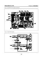
Страница 6: ...aceMate II CTR Controls and Indicators Figure 2 2 Typical Wiring Diagram 30VDC 0 1A 500mW MAX LOCAL ALARM 12 277VAC 0 5A 277VAC MAX 0 1A 30VDC MAX 0 5A 277VAC MAX 0 1A 30VDC MAX GF CT1 AMP CT1 RTD1 GND STUD DC NC ALM AMP CT2 RTD2 NO COM NC HEATER 1 RTD 1 PIPE ...

Страница 7: ...e C 6 30 50 8 30 40 10 24 50 12 16 50 The supply voltage must be single pole 120VAC for TM 2SIH1 RTD single pole 240VAC for TM 2SIH1 RTD 240V dual pole 208 240VAC for TM 2DIH2 RTD 208 240V and single pole 277VAC for TM 2SIH1 RTD 277V Wiring methods must conform to Class 1 Division II or Class 1 Zone II requirements Heater Wiring Connect heating cable wiring to terminals 3 4 for heater 1 and 19 20 ...

Страница 8: ...on output rated 30Vdc 100mA 500mW max The Form C dry alarm contact is rated 0 5A 277Vac 0 1A30Vdc max These alarm outputs are designed to interface to annunciator panels PLC or DCS Figure 2 5 Enclosure and Mounting Dimensions Warning Explosion Hazard Substitution of components may impair suitability for Class 1 Division 2 or Class 1 Zone 2 Warning Explosion Hazard Do not disconnect equipment unles...

Страница 9: ...sonnel can be dispatched to the area The heat trace point with a problem can be identified by the alarm messages on the LCD display For a fast diagnosis and repair the alarm message on the displayand the status LED indicators in the TraceMate II CTR identify the exact nature of the problem This simple connection minimizes control room panel space allowing a few LCD displays and indicators to cover...

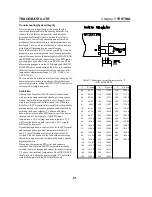
Страница 10: ... very important that the alarm outputs be used so corrective action can be taken quicklyenough to prevent a process shutdown due to the loss of heat to a pipe Ground fault detection only works with resistance or solidly grounded systems If the system is ungrounded it must be grounded or an artificial ground must be created by means of a zip zag transformer Once a ground fault condition is detected...

Страница 11: ...o Figure 2 1 This is useful for checking correct operation of the control If the ground fault alarm light or RTD fail alarm light is on the heater will not switch on even if the actual temperature is below the setpoint Alarm Reset The low high temperature and RTD fail alarms reset as soon as the condition disappears The ground fault trip and current fail alarm are latched alarms A latched alarm wi...

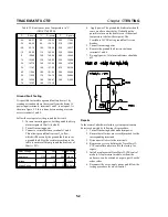
Страница 12: ... installed or for periodic maintenance checks system operation can be verified by adjusting the heater setpoint 2 C above and below a known temperature on the RTD input to see if the heater turns on and off For example if the RTD input temperature is 25 C setting the heater setpoint to 27 C will force the heater on and conversely a 23 C setpoint will force the heater off By substituting a known re...

Страница 13: ...y the ground fault sensor as a ground fault Size the resistor according to the table to ensure sufficient ground fault current of 30mA 25 Heater Voltage 110 240 277 AC Volts Resistance 2700 6200 6800 Ohms Wattage 5 10 15 Watts Voltage Rating 250 500 500 DC Volts 4 Applypower The ground fault indicator should come on after a short delay It should not be possible to turn on the heater even if the ac...

Страница 14: ...OVIDED FOR IN WRITING IN THIS WAR RANTY EACH CONTROL IS PROVIDED WITHOUT ANY WARRANTY OF ANY KIND EITHER EXPRESSED OR IMPLIED IN PARTICULAR WITH OUT LIMITING THE GENERALITY OF THE FOREGOING THE FOLLOW ING IMPLIED WARRANTIES AND CONDITIONS ARE EXPRESSLY DIS CLAIMED a ANY IMPLIED WARRANTY OR CONDITION THAT THE CON TROL WILL MEET YOUR REQUIREMENTS b ANY IMPLIED WARRANTY OR CONDITION THAT THE OP ERATI...

Страница 15: ...TRACEMATE II CRT ELECTRONIC THERMOSTAT P N 1501 0014 TM II CTR 08 07 Printed in Canada Nextron Corporation 6120 11th Street S E Calgary Alberta T2H 2L7 Tel 403 735 9555 Fax 403 735 9559 ...

Отзывы: