TRACE
MATE II-CTR
2.3
Chapter 2 Installation
Mounting the Controller
Mount the control panel with Unistrut brackets using
5/16” bolts. The Unistrut (or equivalent) mounting allows
air circulation to cool the heat-sink. This is important to
ensure proper operation of the TraceMate II-CTR.
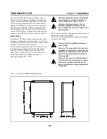
Mounting dimensions are shown in Figure 2.5.
Wire Sizing
Conduit and Cabling
TraceMate II-CTR comes with two 0.843” and one
1.125” conduit knockouts located on the bottom of the
enclosure. Conduit hubs should be NEMA-4X rated, such
as T&B H075-0.75 and H125-1.25 or Myers equivalent,
to maintain a watertight seal. Unused knockouts should be
sealed using NEMA-4X rated seals.
Power Wiring
The power input terminals supply power to both the heat
trace and controller. Size the power input wires
appropriately to the breaker size and maximum ambient
operating temperatures. Maximum breaker size is 30A.
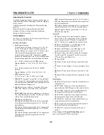
Connect power wires to input terminals 1 & 2 for heater 1
and 17 & 18 for heater 2. See Figure 2.2. The breaker
should be placed as close as possible to the TraceMate II-
CTR.
The RTD probe is delicate and should not
be bent or used as a tool to puncture
insulation.
Wiring methods should comply with Canadian
Electrical or National Electrical Code and
local codes. Power and signal wires should not
be run in the same conduit system. Wiring
should be rated at least 90 °C, 300 V Min.
Wire Size (AWG)
Current Load (A)
Max. Ambient
Temperature (°C)
6
30
50
8
30
40
10
24
50
12
16
50
The supply voltage must be single-pole
120VAC for TM-2SIH1-RTD, single-pole
240VAC for TM-2SIH1-RTD-240V, dual-pole
208~240VAC for TM-2DIH2-RTD-208~240V,
and single-pole 277VAC for TM-2SIH1-RTD-
277V.
Wiring methods must conform to Class 1,
Division II or Class 1, Zone II requirements.
Heater Wiring
Connect heating cable wiring to terminals 3 & 4 for
heater 1 and 19 & 20 for heater 2. See Figure 2.2. If the
heating cable has a braid, it should be terminated to the
ground stud using a ring terminal suitable for #10 stud.
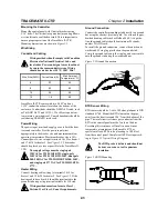
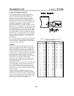
Figure 2.3 Ground Connection
Ground Connection
Connect the controller grounding stud directly to a ground
bus using the shortest, practical path. Use a tinned copper,
braided bonding cable such as Belden 8660. As a guide-
line, the ground cables should be minimum 96 strands,
number 34 AWG each.
To install the ground connection, remove the outside nut,
washer and #8 ring lug provided on the ground stud.
Crimp the ground cable onto the ring lug and re-assemble
onto the ground stud using the washer and nut.
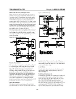
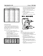
Figure 2.4 RTD Mounting
RTD Sensor Wiring
RTD sensors should be 3-wire, 100 ohm, platinum to DIN
standard 43760. Mount the RTD element on the pipe,
away from the heat trace and 180° from the bottom of the
pipe. The total circuit resistance per conductor from the
RTD to the control panel must be less than 10 ohm.
Exceeding this resistance will result in a non-linear
temperature measurement. Beldon cable 8770 or
equivalent allows RTDs to be placed up to 1,000 feet
from the control panel. Complete all RTD wiring accord-
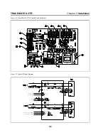
ing to Figure 2.2 Typical Wiring Diagram.


