N560 series H/W Installation Guide
NexComm Systems, Inc. 13 PAGE
LED State
Description
GREEN
(0~3)
Off
Data Link Down or Hand Shaking
Slow Blinking
Training
Fast Blinking
Synchronizing
On Data
Link
Up
YELLOW(S0)
Blinking
S0 (Pair 0~1) binging data is being tranceived
YELLOW(S1)
Blinking
S1 (Pair 2~3) binging data is being tranceived
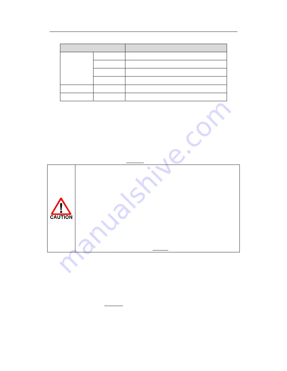
< Table 2-8 > Indication of 2BASE-TL LEDs(Dual Interface Over DSL)
3
Installing N560 series
This section guides how to install N560 series. User may be aware of the safety information in order to
assure users’ safety and N560 series’ good performance. Attention required procedures will be
accompanied with safety marks, one of the Table A-1.
User should choose a proper place in which the equipment will operate.
The surrounding temperature must be in range of 0
℃
~ 40
℃
and high humidity
must be avoided.
Basically, N560 series emits a considerable amount of heat. User should take
care of the N560 series’ ventilation.
Do Not stack N560 series or block any
slits on the N560 series’ case
.
Avoid a direct ray of light and electrical interference.
Do not touch the pins of the connectors.
Do not handle N560 series while you are wearing metallic accessories on hands.
Do not disassemble N560 series. It may cause damage to the chips contained.
Dealing with a problem, user may refer to section 6.
3.1
Checking in the Box
Following items are needed, in addition to the main device, for the set-up of N560 series:
-
DC adaptor ( 5V DC 3A )
-
UTP cable with RJ-45 for LAN connection
-
Console cable ( RJ-45 male to DB-9 female )
Above items are described in Figure 3-1.


