background image

P.O. Box 1306

Newport Beach

California 92663


Phone: 714-751-0488  

     Fax: 714-957-1621

     E-Mail: [email protected]

www.newmartelecom.com

MATERIALS PROVIDED

The MDP-25.0 is supplied with the following materials:

(4) # 8 ring lugs for 8 gauge wire 

(1) Terminal block cover (attached)

(1) Installation/Operation Manual         

Check to see that these have been included with the packaging. For any missing items, please contact Factory.

INSTALLATION
Mechanical:

Locate a flat surface close to the power line that feeds the electronics. For best results, the MDP should be within 24” of 

the critical electronics. The case need not be grounded, so it is acceptable to mount the unit on wood or metal. Securely 

mount the unit in any orientation, however horizontal is best. 

Note: 

In order to ease future battery replacement, it is 

recommended that the front of the MDP remain un-obstructed.

Power:
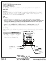
Input wiring: 

1) Remove both Input and Output fuses on MDP (ATC-30 x 2) before installation. Remove terminal block cover.

2) Turn off the power on the input wires by disconnecting the battery or shutting off the appropriate circuit. Note, the MDP   

  functions as an uninterruptable power source. If electronics are wired directly to the MDP output and the primary  


  feed voltage to the MDP is via an ignition switch, when the switch is turned off the MDP will continue to power the  


  load until its internal battery reaches a low voltage disconnect point.

3) Identify the positive and negative lead in the power line and cut at an appropriate location. Use the lugs   

    supplied, wire the input to the MDP – note it is recommended that the input be fused at the source, see 

    illustration below. 

Output wiring: 


Using the table below, select the proper wire size for your installation and attach to terminal block. Four rings lugs for 8 

AWG wire size are included with the MDP-25.0. Replace terminal block cover to prevent accidental shorting of the 

terminals.

3

(+)

(-)

DC Input

(Connect to fused, 

unswitched DC source 

or one which always 

stays on)

To Critical 

+12V loads

To Critical -12V 

loads

Circuit Breakers / Fuses

(Optional)

Ground

POSITIVE

GROUND


AMPS*                               

CABLE LENGTH (feet)                                           

10’

15’  

     0 - 10 

AMPS

12 AWG    

10 AWG  

    10 - 25 AMPS                   

8 AWG   

8 AWG

* Current draw of Electronics being powered.


>

Fig. 1: Input and Output Wiring

Содержание MDP-25.0

Страница 1: ...Materials Provided 3 Installation 3 Mechanical Power Wiring Signal Wiring Motorola Output Settings Default and Optional Operation 4 Status LEDs Disconnect Timer TMR Operation Advanced Settings Backup...

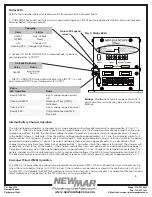
Страница 2: ...Fax 714 957 1621 E Mail techservice newmarpower com www newmartelecom com Quick Reference Guide Status LEDs Page 5 Status LED Legend Page 5 D Sub 9 Pin Motorola Interface Page 4 Input Output Wiring P...

Страница 3: ...engine is off Allows use of accessory loads per programmed time limit user adjustable while preserving battery for emergency starting Factory default is not active see page 5 Built in LVD Low Voltage...

Страница 4: ...nput wires by disconnecting the battery or shutting off the appropriate circuit Note the MDP functions as an uninterruptable power source If electronics are wired directly to the MDP output and the pr...

Страница 5: ...on of voltage occurs augmenting voltage to the electronics for 3 seconds If proper primary voltage is not restored within the 3 second time frame input from the vehicle battery disconnects and electro...

Страница 6: ...nce the battery voltage reaches approximately 14 2 volts the charging current will start to reduce The voltage will remain at 14 2 volts stage 2 high rate absorption charge until the current to the ba...

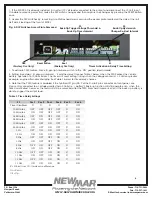
Страница 7: ...s 5 Note that the TMR feature is disabled if the Ignition IN pin Pin 2 of the D sub 9 pin connector on front panel see Figure 2 is connected to a voltage greater than 2 volts i e battery Back up funct...

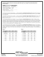
Страница 8: ...internal battery see table 4 Hysteresis should be set after determined the amount of voltage drop from the DC source vehicle battery to input terminals of the MDP when the intended output load curren...

Страница 9: ...battery loosen and back out the four front Battery Access Plate securing screws and remove Battery Access Plate Once the plate is removed you will see the battery is secured in position by a Locking...

Страница 10: ...N If a problem persists after you have applied the above outlined solutions or if you have any questions about the installation and proper operation of the MDP 25 0 please contact NEWMAR s Technical S...

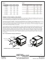
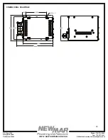
Страница 11: ...Box 1306 Newport Beach California 92663 Phone 714 751 0488 Fax 714 957 1621 E Mail techservice newmarpower com www newmartelecom com DIMENSIONAL DRAWINGS 6 980 8 460 5 400 4 750 300 6 000 281 x 4 5 79...

Отзывы: