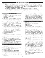
Linking Cable from Pong-Master
Scoreboard (optional) plugs in here
CONTROL BOX FOR 1040+/2040+
TOP VIEW
FIGURE 1A
1
3
4
2
If you open Control Box, remove ONLY these 4 screws
Connector Cable from
robot plugs in here
Pin of Transformer
plugs in here
CONTROL BOX FOR 545
TOP VIEW
FIGURE 2A
CONTROL BOX FOR 545
REAR VIEW
1
3
2
Connector Cable from
robot plugs in here
Pin of Transformer
plugs in here
7
OPERATION OF YOUR ROBOT
Your robot is extremely versatile and fully adjustable to
suit a wide variety of playing abilities and styles. Ball
speed, frequency, spin, trajectory, and placement can all be
adjusted, as well as oscillator speed and range. The follow-
ing section will explain the various controls and adjust-
ments of your robot.
CONTROL BOX (ALL MODELS)
The robot’s motors are controlled electronically by the
Control Box. Figures 1A and 1B illustrate the functions and
controls for the 1040+ & 2040+ models. Figures 2A and 2B
illustrate the functions and controls for the 545.
1. POWER—Used to turn the robot “ON” or “OFF”.
2. BALL SPEED—Regulates the ball speed and spin.
Higher settings increase the amount of spin and forward
speed on the ball. On the 545, this control also functions as
the on/off switch. See also Ball Trajectory on page 7.
3. BALL FREQUENCY—Regulates the time between
shots. Lower settings increase the time between shots.
Higher settings decrease time between shots. Lowest set-
ting at which balls will come out is approximately 2 (13 to
26
balls per minute). At a setting of 10, the robot delivers
approximately 90 balls per minute for the 1040+ & 2040+
models and 60 balls per minute for the 545.
4. OSCILLATOR SPEED—Regulates the speed at
which the robot head sweeps side to side. Higher settings
make the head sweep faster. This control is also used to
position the head in the desired direction when you want
balls to be delivered to one spot. First set the control levers
on the rear of the robot to positions 3 & 4 (see page 9). Turn
Oscillator Speed on, and when the head reaches the desired
position, turn it off. See also Figures 3A & 3B below.
WARNING: Use the Oscillator Speed control to make the
robot head move sideways. DO NOT attempt to move the robot
head sideways by hand. Doing so will likely result in broken
parts and may void your warranty.
FIGURE 2B
CONTROL BOX FOR 1040+/2040+
BOTTOM VIEW
FIGURE 1B
FIGURE 3A
FIGURE 3B
Because oscillator speed has not
been set correctly, the second ball is
placed too closely to the first ball.
This results in not having to move the
feet very much.
Oscillator speed has been adjusted
so the second ball lands well away
from the first ball. This makes the
player move the feet a greater
distance, resulting in better footwork
and more exercise.
1
2
1
2
INCORRECT OSCILLATOR SPEED
(1040+/2040+ ONLY)
CORRECT OSCILLATOR SPEED
(1040+/2040+ ONLY)
Содержание Robo-Pong 1040+
Страница 27: ...TRAINING LOG 27 DATE TIME NOTES...
Страница 28: ...28 DATE TIME NOTES...


