background image

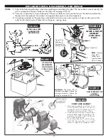
ROBOT HEAD 

TO PIVOT 

GUIDE

5-PIN CONNECTOR

BALL FEED UPPER 

GUIDE TO BACK 

PANEL

When  attach ing 

the Oscillator 

Motor Cover 

(83) to the robot, 

move the 

Oscillator 

Control Levers 

(81 & 82) to 

positions 1 and 

6 (see page 9). 

This makes it 

easier for the 

oscillator drive 

shaft to fit 

between the 

levers.

OSCILLATOR COVER 

TO UPPER GUIDE

24

FIGURE F

FIGURE G

FIGURE H

FIGURE I

73

(To Ball 

Speed Motor)

53

(To Ball Feed Motor)

Red

Black

(w/Tracer)

White

(Or Black)

Black

(w/Tracer)

Robot

Head

Robot Head

Black

(No Tracer)

Black

(No Tracer)

87

(To Osc. 

Motor)

545

ONLY

1040+/2040+

ONLY

79

71

67

68

68

59

74

80

79

82

81

57

57

39

39

92

93

93

83

84

93

69

70

73

Red Wire Attaches 

To Terminal With 

Polarity Marker

60

See 

Note 

#2

78

See

Note #1

65

64

72

74

63

58

77

See 

Note #3

61

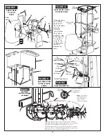
FIGURE E

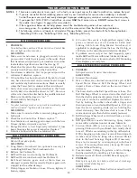
     ROBOT HEAD ASSEMBLY

1. When disassembling the robot head, do not

let the Detent Pin (65) fall out of the Left

Housing (61) since it's small and easy to lose!

Work atop a towel to prevent loss of parts.

2. A small amount of Superglue

®

  (cyano acry late)

holds the Ball Discharge Spring (60) onto the

Discharge Tube (58). Scrape off old glue

before replacing the spring.

3. Keep Friction Block (77) and Discharge

Wheel (75, Figure D) clean for correct ball

speeds. See page 20 for cleaning procedure.

Page 5 of 6

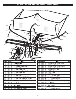
BALL FEED

MOTOR & GEARS 

ASSEMBLY

FIGURE J

Tracer Wire Attaches 

To Terminal With 

Polarity Marker

Yellow transfer gear (89) is closest to pinion gear of the Ball 

Feed Motor (51) and green transfer gear (49) is closest to Main 

Gear (46). When replacing any plastic gear, be sure to 

lubricate the gear and gear post with silicone 

grease

 to reduce 

gear noise. Do not use petroleum based lubes or sprays as those 

chemicals are corrosive to the ABS plastic parts.

Polarity 

Marker

53

52

93

45

93

45A

50

48

47

42

46 44

93

41

39

89 49

51

93

54

CORRECTIONS TO PAGE 25

Note

: Screw #45 is 

left-hand threaded

Turn clockwise to 

loosen; counter-

clockwise to tighten.

Содержание Robo-Pong 1040+

Страница 1: ...g Instructions Carefully Newgy Table Tennis Robot OWNER S MANUAL For Models 2040 1040 545 Manufactured under one or more of the following U S patents 4 844 458 4 854 588 4 917 380 5 009 421 5 335 905...

Страница 2: ...arranties with respect to the contents of this manual and expressly waives any implied warran ty for the particular purpose of sale or interest The manufacturer reserves the right to make any amendmen...

Страница 3: ...ies parts replacement service and warranty In general instructions will apply to all models except when clearly designated by a caption heading or the following footnotes 1Robo Pong 1040 only 2Robo Po...

Страница 4: ...end in a horizontal position If you re right handed place it on the left side of the table If you re left handed place it on the right side of the table Open the clip and place the Connector Cable and...

Страница 5: ...ready for random delivery turn the Oscillator Speed on and the balls will be randomly delivered across the entire table To become more familiar with the controls and adjustments for your machine read...

Страница 6: ...th the table and the Front Support Plate sits on top of the table The center of the Front Support Plate aligns with the centerline of the table The robot will be held by its own weight See Figure 10 p...

Страница 7: ...r settings increase the time between shots Higher settings decrease time between shots Lowest set ting at which balls will come out is approximately 2 13 to 26 balls per minute At a setting of 10 the...

Страница 8: ...um Ball Speed is 3 5 As the Ball Speed is turned up the head must be angled up to deliver the ball so it first strikes the player s side of the table robot returning see Figures 6A 6B As the Ball Spee...

Страница 9: ...From Position Shown SPIN SELECTION FIGURE 7 TOPSPIN SIDE VIEW BACKSPIN SIDE VIEW P A D D L E PADDLE LEFT SIDESPIN TOP VIEW RIGHT SIDESPIN TOP VIEW RETURN SHOT RETURN SHOT RETURN SHOT PADDLE PADDLE RET...

Страница 10: ...lure to follow these instructions will likely result in broken parts and may void your warranty Following is an explanation of each zone that can be selected as shown in Figures 10 and 10A 3 4 Robot d...

Страница 11: ...the playing area and place them inside the box too REMOVE CLEAR FRONT COVER Place the robot body on your table Pull the Clear Front Cover off by squeez ing on the circular fingerholds on the sides of...

Страница 12: ...roll down into the Center Trough The balls will be out of the way and you can easily loosen the two wing nuts and two clip washers then pull up on the robot body to remove it see Steps 4 5 opposite p...

Страница 13: ...er s end At a Ball Speed setting of 10 the ball speed is very fast and simulates the angle from which a typical kill shot would be hit However the 1040 s oscillator ranges are narrower than if the rob...

Страница 14: ...ake sure the robot sits level by adjusting the Rubber Tips as described above In this case it may be necessary to use the Rubber Tip one size larger than normal to level the robot ADJUSTING NET TENSIO...

Страница 15: ...the flexible band 21B Insert the band into the clip where the knot is located 21C Side Net should look like 21D The flexible bands were designed to provide the proper tension for the side nets in most...

Страница 16: ...tting them in the Ball Bucket or Ball Trays run the balls through the machine at high frequency by setting the Ball Frequency to 10 the Ball Speed to 3 the spin to backspin and aim the head at the mid...

Страница 17: ...VE BALL DAMS F r o m t h e front of the robot raise e a c h t r a y slightly and remove the Ball Dams from their storage posi tions Don t raise too much or the balls will fall out See Figures 11 13 on...

Страница 18: ...s if you purchased that accessory When in serting the targets into the pocket target wires should be furthest down in the pocket to prevent the weight of the wires from bending the edges of the target...

Страница 19: ...he plastic Be careful not to get water on the motors Control Box or the 5 Pin Connector REMOVE ROBOT BODY First remove the robot body from the Center Trough 2040 or Ball Bucket 545 1040 Then lay it on...

Страница 20: ...ill not pick up balls SOLUTIONS A Pong Master Scoreboard an optional accessory is controlling Ball Feed Turn Scoreboard off 1 2 B Ball jam See Problem 18 C Ball Feed Motor is not running See Problem 1...

Страница 21: ...r the ball all the way to either the left or right corner of the table when spin is set to straight topspin or backspin Control Levers are set to positions 3 4 and robot is in position 1 or 5 Figure 1...

Страница 22: ...e Control Box is bad Replace 1 2 BALL JAMS 18 PROBLEM Balls jam inside the machine Ball jams are normally indicated by a squealing noise from the Control Box SOLUTIONS A See Solution 6A B Using new or...

Страница 23: ...er 60 See Note 2 78 See Note 1 65 64 72 74 63 58 77 See Note 3 61 FIGURE E ROBOT HEAD ASSEMBLY 1 When disassembling the robot head do not let the Detent Pin 65 fall out of the Left Housing 61 since it...

Страница 24: ...n 65 fall out of the Left Housing 61 since it s small and easy to lose Work atop a towel to prevent loss of parts 2 A small amount of Superglue cyanoacrylate holds the Ball Discharge Spring 60 onto th...

Страница 25: ...1 2000 116 CT Support Leg Rubber Tip 3 4w std 2 12 2000 118 CT Support Leg Rubber Tip 1w 2 13 2000 120 CT Rubber Spacer Washer not shown 4 14 2000 122 CT Pivot Pin 1 15 2050 124B CT Ball Dam 40 mm 2 1...

Страница 26: ...I pg 25 1 54 2040 161B BF Spring Short 1 55 2040 162A BF Clear Front Cover 40mm 1 57 2040 164B BF Upper Guide 40 mm 1 58 2040 166A BF Discharge Tube 40mm 1 59 2000 168 BF Discharge Tube Brake 2 60 20...

Страница 27: ...TRAINING LOG 27 DATE TIME NOTES...

Страница 28: ...28 DATE TIME NOTES...

Страница 29: ...performing a Factory Default Restoration pg 14 You may also want to visit our website to see if any information has been updated When you do call please have your serial number and this manual handy T...

Отзывы: