Section-3
www.newavenergy.com
04-1206_S3_NW_OPMPS_10-50kVA_GB_110201.doc
Page 2/4
Printed in Switzerland – Modifications reserved
3.1 INTERFACING
Each UPS is provided with communication port and a communication card, which provides system information
STANDARD ITEMS
RS232 on Sub-D9 port
For monitoring and integration in network management
Customer Interfaces :
Inputs DRY PORT
1 Remote Shut down [EMERGENCY OFF (Normally closed)]
1 GEN-ON (Normally open)
1 Programmable Customer’s Inputs (Normally open)
1 Temp. Sensor for Battery Control
1 12 vdc source (max. 250 mA)
RJ45 port
For multidrop purpose
Power Management Display (PMD)
LCD display
OPTIONAL ITEMS
Relay card + USB Including:
Customer Interfaces:
5 output DRY PORTS
RS232 on USB port
•
Common
alarm
•
Load on bypass
•
Battery
low
•
Load on inverter
•
Mains
failure
For remote signalling and automatic computer shutdown
SNMP Card (slot already included)
SNMP card
For monitoring and integration in network management
3.1.1 SMART PORT JD1 (SERIAL RS 232 / SUB D9 / FEMALE) AND USB PORT
The
SMART PORT JD1
and
USB port
located on the UPS itself is an intelligent RS 232 serial port that allows the
UPS to be connected to a computer. The connector is a standard D-Type, 9-pin, female, and the USB is a standard
USB port.
When installed the optional SMART PORT, the software WAVEMON allows the computer to monitor the mains
voltage and the UPS status continuously.
In the event of any changes the computer terminal will display a message. (For details see our Monitoring
Package:
WAVEMON
).
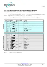
The Fig. 1.1 shows how to connect a PC to the UPS with different Sub-D connectors.
a)Interface Cable (UPS End)
Interface cable (Computer End)
(9-Pin, D-Type female)
(9-Pin, D-Type male)
Connects UPS
Connects to
to SMART PORT
Computer
1
2
3
9
.
.
5
1
2
3
9
.
.
5
Figure 1.1 Connector Cable - PC Serial Port with 9-Pin Connection

