Section-2
www.newavenergy.com
04-1206_S2_NW_OPMPS_10-50kVA_GB_110201.doc
Page 4/14
Printed in Switzerland – Modifications reserved
2.2
FRONT and REAR VIEW
2.2.1 FRONT AND REAR VIEW OF POWERSCALE CABINET A
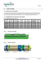
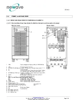
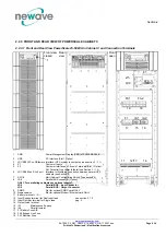
2.2.1.1 Front and Rear View PowerScale 10-20kVA in Cabinet A and Connection Terminals
FRONT VIEW
REAR VIEW
1
PMD
Power Management Display (PMD) of POWERSCALE
2
USB
PC Interface (Slot 1 Option)
3
JD1/RS232 Sub D9/female Interface (UPS system to computer) (see section 3 / 1.1)
4
X1
Customer Inputs
5
X2
Customer interface on Phoenix Terminals (Slot 1 Option):
X2= Potential free contacts (detail see Section 3 / 1.2 )
6
JR1/RS485 on RJ 45 port Interface for Multidrop connection between several UPS
cabinets (see Section 3)
7
SW1-9
Multi-Cabinet Configuration Switch (see section 4)
8
JD8
Parallel BUS connector (Option)
ONLY For paralleling cabinets use optional adapter:
JD5
Parallel BUS - Input Connector
JD6
Parallel BUS - Output Connector
9
SNMP
Slot for optional SNMP card ONLY
10 Newavewatch
Slot for optional Modem/Ethernet card ONLY
11 Battery te / N / -
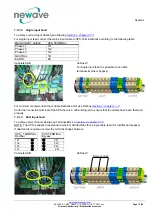
12 Input Rectifier terminal for Single feed
see section 2.1.2
13 Input Bypass terminal for Dual Input feed
pag.2
14 Output Load terminal
15 IA1
Maintenance Bypass
16 IA2
Parallel
Isolator
17 FA3 Battery Fuse A/B
18 FA2 Bypass Line Fuse
19 FA1 Rectifier Fuse
1
1
8
2/5
9/10
3
4
7
6
17
19 18
15
16
11 12
13
14
FA3

